Crank engine and observe results at spark tester.
• If there
is
no spark at one gap, go to Power
Pack Cranking Output
on
p.
124.
• If there is no spark at both gaps, go to Charge
Coil Test
on
p.
122.
• If the spark jumps alternately at each gap, the
problem is
in
the stop circuit. Begin trouble-
shooting with Ohmmeter Test and follow all
steps to locate the fault.
Ohmmeter Test
Step 1
IMPORTANT:
All
ohmmeter tests must be per-
formed with the engine
NOT running.
Install the clip and lanyard.
Calibrate
an ohmmeter
on
appropriate scale. Con-
nect meter
leads between ignition plate end of
connector,
terminal "E," and a clean engine
ground.
• The meter must show a high reading.
DR4186
Momentarily press inward
on
the stop button.
• The meter must show a low reading.
Remove the emergency stop switch
clip and lan-
yard.
• The meter must show a low reading.
• If any of the test results are incorrect, replace
STEP
2
IGNITION
IGNITION SYSTEM TESTS
Install the emergency stop switch clip and lanyard.
Disconnect the 5-pin Amphenol connector
between the power pack and ignition
plate.
Calibrate
ohmmeter
on
appropriate scale. Con-
nect meter
leads between ignition plate end of
connector,
terminal "E," and a clean engine
ground.
• Key
OFF,
meter must show a low reading.
• Key ON, meter must show a high reading.
If key
ON
reading
is
a low one, disconnect har-
ness
black/yellow lead from key switch "M" termi-
nal.
• If
meter now shows a high reading, replace key 5
switch.
• If meter shows a low reading, go to STEP
3.
STEP 3
Disconnect the key switch 6-pin connector
• If meter now shows a high reading, repair or
replace key switch harness.
• If meter shows a low reading, go to STEP
4.
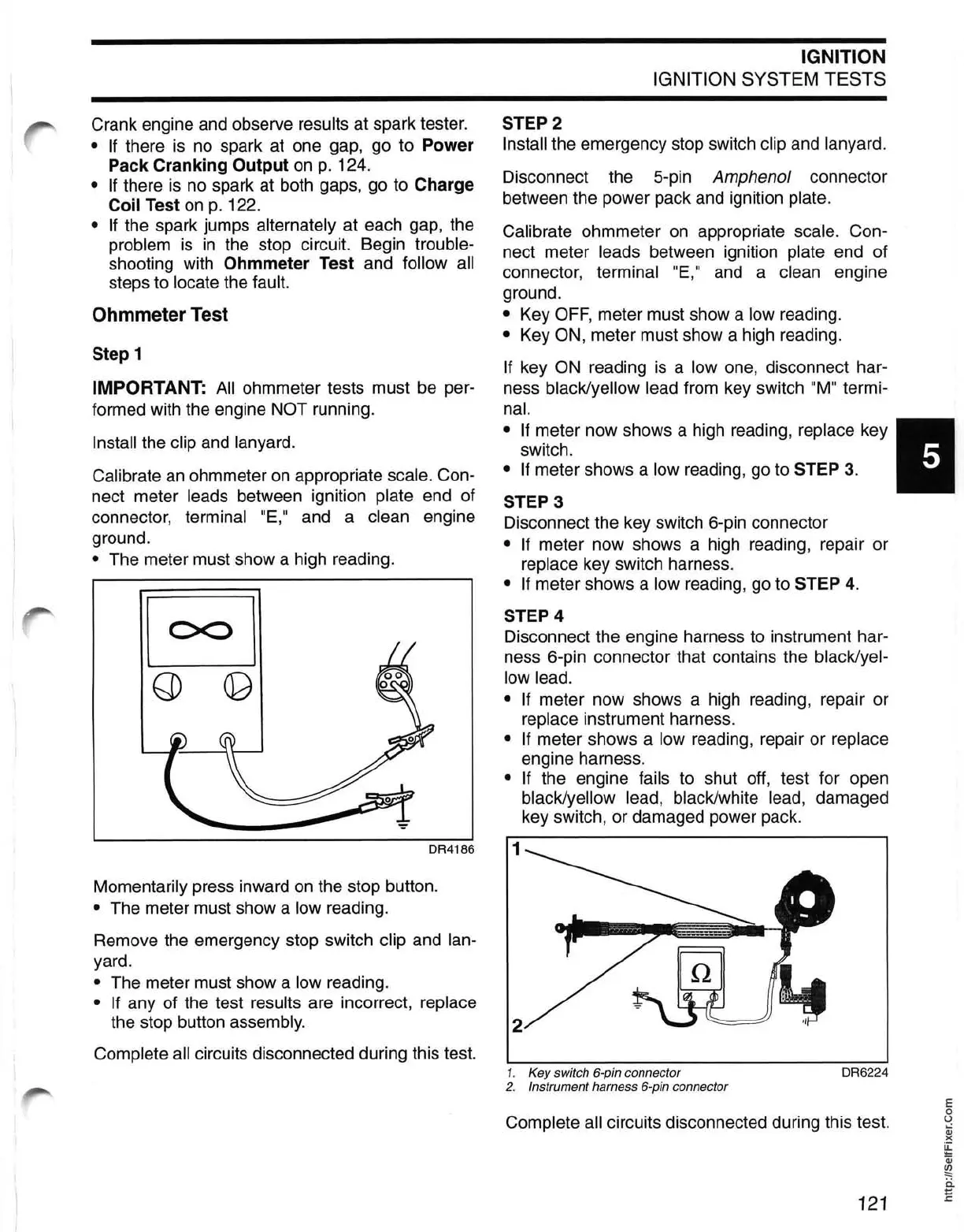
STEP 4
Disconnect the engine harness to instrument har-
ness 6-pin connector that contains the
black/yel-
low lead.
• If
meter now shows a high reading, repair or
replace instrument harness.
• If meter shows a low reading, repair or replace
engine harness.
• If the engine fails to shut off, test for open
black/yellow lead, black/white lead, damaged
key switch, or damaged power pack.
1
the stop button assembly. 2
Complete all circuits disconnected during this test.
1.
Key switch 6-pin connector
DR6224
2.
Instrument harness 6-pin connector
Complete all circuits disconnected during this test.
121
E
o
U
Qj
)(
~
Qj
~
ii
E