IGNITION
IGNITION SYSTEM TESTS
STEP 2
Calibrate ohmmeter
on
appropriate scale. Con-
nect meter
red
lead to coil primary terminal. Con-
nect meter
black lead
to
coil spark plug terminal.
• Meter must show 275 ±
50
ohms
DR4094
STEP 3
Test spark
plug leads for continuity. Calibrate
ohmmeter
on
low ohms scale. Attach one ohmme-
ter
lead to each spring terminal. While wiggling
both spark plug covers
and
entire length of the
spark
plug lead, the resistance should remain
near zero. Replace spark plug lead if your test
results vary.
126
Ignition
Coil
Analyzer
Tests
IMPORTANT: When conducting these tests to
the coil, do not exceed its maximum specified
amperage.
Magneto C.D.
Coil Specifications
Operating
Merc-O-Tronic Stevens
Amps
(Max)
1.5 amps
1.1
amps
Analyzer
Normal
Polarity
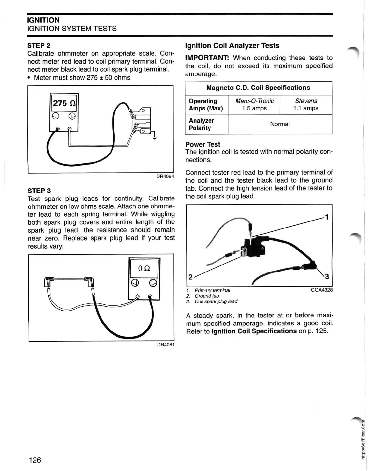
Power Test
The ignition
coil
is
tested with normal polarity con-
nections.
Connect tester
red
lead
to
the primary terminal of
the
coil
and
the tester black lead to the ground
tab.
Connect the high tension lead of the tester to
the
coil spark plug lead.
1
2
3
1.
Primary terminal
C0A4328
2. Ground
tab
3. Coil spark plug lead
A steady spark,
in
the tester at or before maxi-
mum
specified amperage, indicates a good coil.
Refer to Ignition Coil Specifications
on
p. 125.