Chapter - Optional Equipment
Page Issue 02
OG
4:2
V Range 501 ● 651 ● 801 - Operator’s Guide
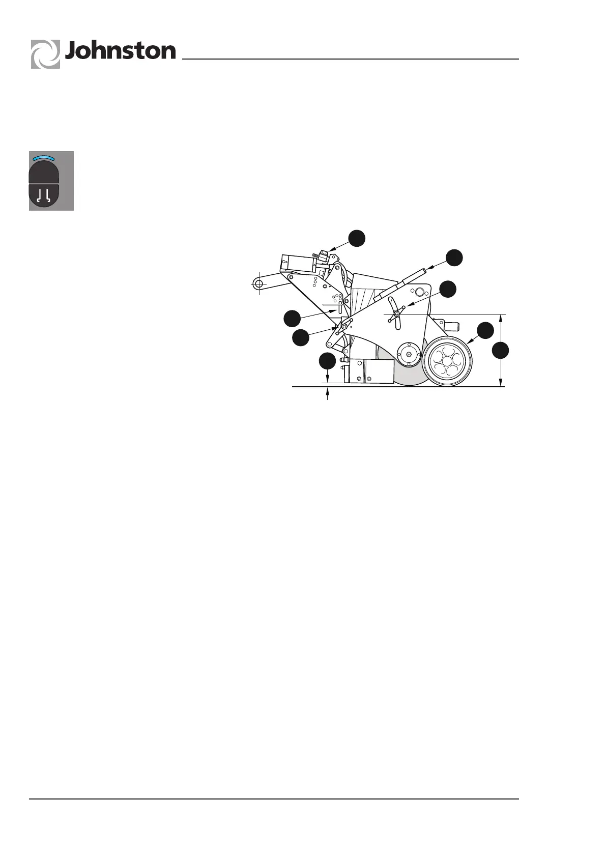
The Combivac nozzle contains a rotating brush and may allow higher sweeping speeds in certain
working conditions.
The Combivac Nozzle features four
water jets as standard, two of which can
be isolated by turning off the manual tap
(G) at the front of the nozzle drawbar.
The pressure of the brush on the road is
achieved by loosening hand nuts (C) and
(D) and raising or lowering by use of the
handle (B). The normal nozzle opening
(F) is controlled by moving pin (A) up or
down the adjustment holes to achieve
the desired opening (nominal 30mm).
To Operate Nozzle With Brush
Lower nozzle, release hand nuts (C) and (D) and lower brush to obtain the desired pressure
on the road. Retighten nuts (C) and (D).
To operate without brush
Lower nozzle, release hand nuts (C) and (D) and raise the brush assembly using the handle
(B). Retighten nuts (C) and (D). Brush should be above the road surface.
NozzleWheelAdjustment
The nozzle wheel (E) is adjustable to compensate for wear. Ensure the dimension (H) is
365mm when a new brush is fitted.
ToAdjustOperatingHeight
Lower nozzle and operate maxigap. This will remove tension from pin (A). The pin can be
moved to the desired hole to set the minimum nozzle opening required.
To Change Brush Segments
i) Lower nozzle to ground. Remove the outer brush carrier plate by removing the two M10
setscrews from the cross tube and the two hand nuts.
ii) Raise the nozzle and withdraw the brush stock.
iii) Undo the end plate of the stock and replace brush segments. On re-assembling, remember
to fit a spacer at each end of the stock.
iv) Refitting is the reverse of the above procedure.
M02OG-104
A
B
C
D
G
E
H
F
COMBIVAC NOZZLE OPTION
Water sprays; - ON/OFF Illuminated when selected
Nozzle; - ACTIVE/STOWED - Nozzle lowers and brush rotates intake flaps open
automatically
A
All Copyright and rights are the property of Johnston Sweepers Ltd