A
C
B D E
F
Before fitting the exchanger or positioning the fireplace, choose
the required electrical assembly diagram from among those
given, then prepare the necessary paths for the connection
cables, obtained from passages in tubes with sheathing for
electrical cables of approved types.
The fan and 230V line cables must not be inserted in the same
sheathing used for the probe (or thermostat) and display cables.
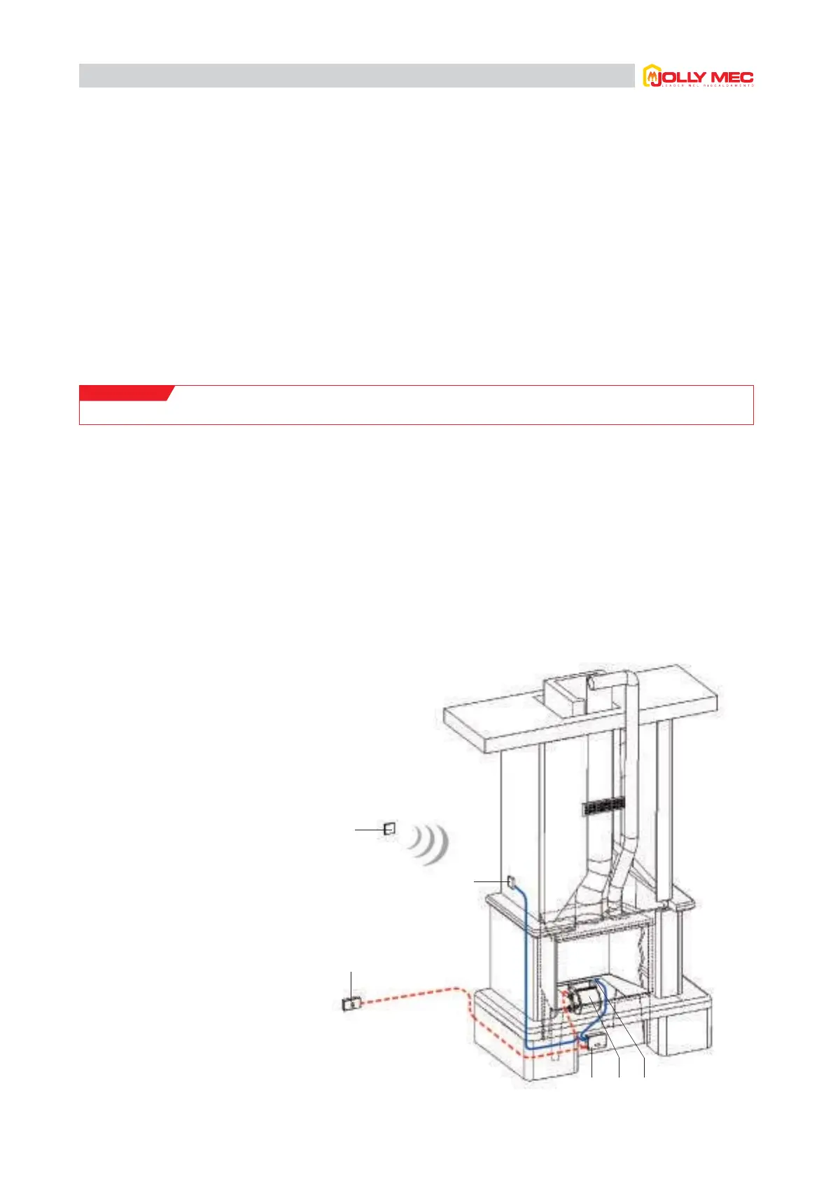
1.1.1 SOLUTION 1: for new fireplaces or inserts
Components
Controller positioned under the fireplace, inside the cladding, or
in the compartment obtained for the fan in already existing
cladding for Universaljolly (see fireplace instructions). Display
positioned at side on cladding hood.
For this important requirement, the following diagrams use the
colour RED
- - - - - -
for 230V cables and BLUE
- - - - - -
for very
low voltage cables.
In the following examples
the
RADIO FREQUENCY remote control
(an OPTIONAL accessory) is represented with n. F.
A
B
C
D
E
F
Main switch
Controller
Command and control
display
Fan
Probe or thermostat
Optional remote control
IMPORTANT!
Always make sure the temperature where the controller and display are placed does not exceed 60°C.
1.1 Recommended assembly diagrams