A
DBCE
F
1.1 Recommended assembly diagrams
6
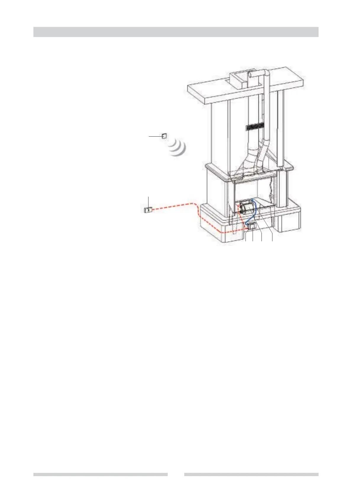
1.1.6 SOLUTION 6: for new fireplaces or inserts with remote control
Components
A
B
C
D
E
F
Main switch
Controller BP07
Command and control
display
Fan
Probe or thermostat
Remote control
Controller and display both positioned under the fireplace inside
the cladding; or in the fan compartment (see fireplace
instructions) for Universaljolly units. Display attached to the
controller box cover with velcro (supplied); or with self-tapping
screws (3.5x9.5), making sure to leave at least 5mm between
the screw and the electronic board in the box.
 Loading...