A
C
B D E
F
A
B
D E
C
F
1.1 Recommended assembly diagrams
4
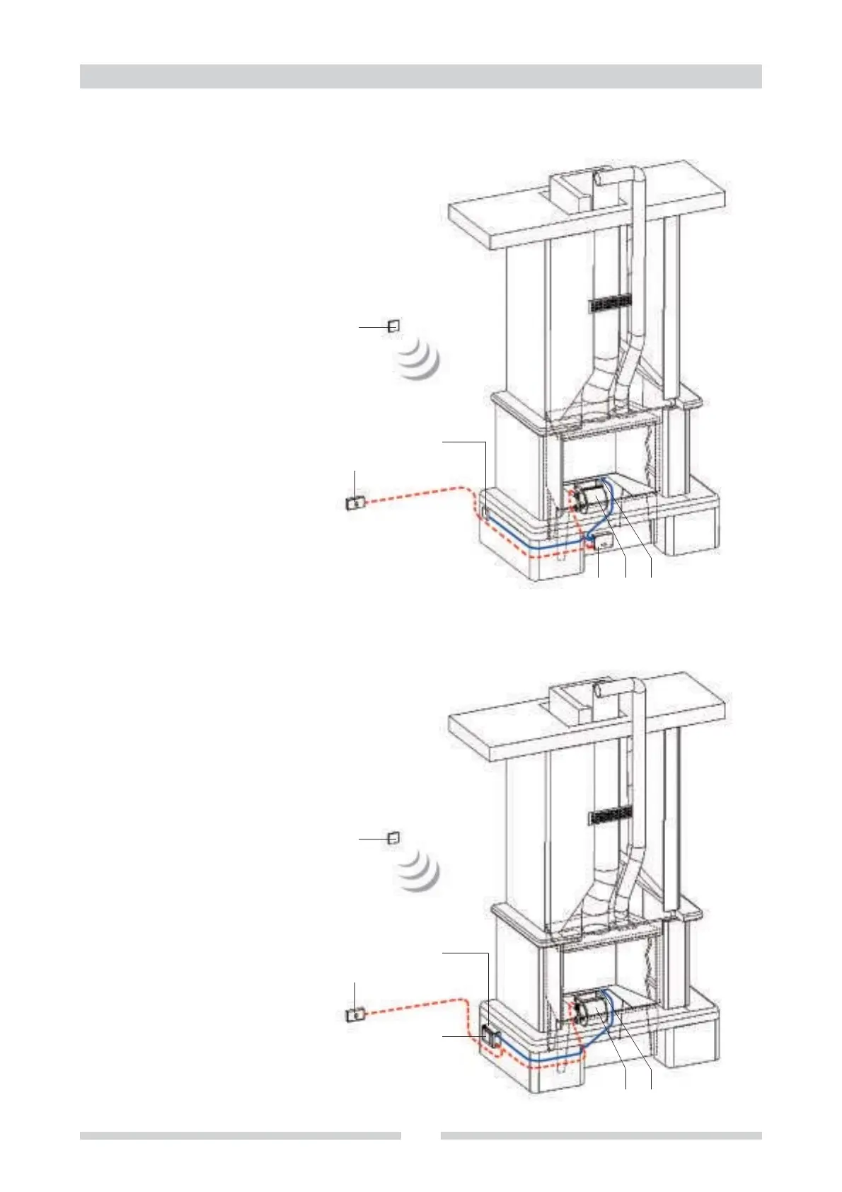
1.1.2 SOLUTION 2: for new fireplaces or inserts
Components
A
B
C
D
E
F
Main switch
Controller BP07
Command and control
display
Fan
Probe or thermostat
Optional remote control
Controller positioned under the fireplace, inside or outside the
cladding, or in the compartment obtained for the fan in already
existing cladding for Universaljolly. Display positioned at side on
the cladding plinth.
1.1.3 SOLUTION 3: for inserts
Components
A
B
C
D
E
F
Main switch
Controller BP07
Command and control
display
Fan
Probe or thermostat
Optional remote control
Controller and display positioned at side on the cladding plinth.
Display attached to the controller box cover with velcro (supplied);
or with self-tapping screws (3.5x9.5), making sure to leave at
least 5mm between the screw and the electronic board in the box.