1.1 Recommended assembly diagrams
5
A
B
C
D E
F
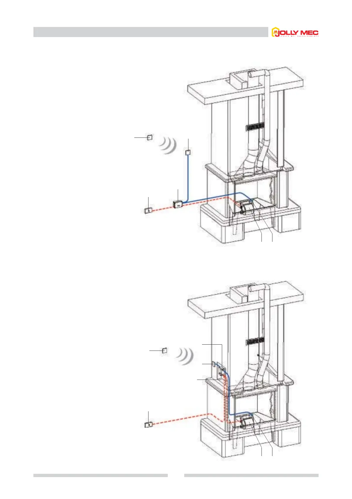
1.1.4 SOLUTION 4: for new fireplaces or inserts
Components
A
B
C
D
E
F
Main switch
Controller BP07
Command and control
display
Fan
Probe or thermostat
Optional remote control
1.1.5 SOLUTION 5: for new fireplaces or inserts
Components
A
B
C
D
E
F
G
Main switch
Controller BP07
Command and control
display
Fan
Probe or thermostat
Optional remote control
Humidifier access recess
A
D E
F
C
B
G
Controller and display away from fireplace, maintaining the
maximum distances recommended in the wiring instructions.
Controller positioned in the fireplace hood, with the display
positioned above it, or elsewhere. N.B.The temperatures where the
controller is placed must be below 60°C.