6
SAFETY NOTICE: Exposure to
vibrations through prolonged use of gasoline
powered hand tools could cause blood
vessel or nerve damage in the fingers,
hands, and joints of people prone to
circulation disorders or abnormal swellings.
Prolonged use in cold weather has been
linked to blood vessel damage in otherwise
healthy people. If symptoms occur such as
numbness, pain, loss of strength, change in
skin color or texture, or loss of feeling in the
fingers, hands, or joints, discontinue the use
of this tool and seek medical attention. An
anti-vibrationsystem does not guarantee the
avoidance of these problems. Users who
operate power tools on a continual and
regular basis must monitor closely their
physical condition and the condition of this
tool.
ASSEMBLY
Protective gloves (not provided) should be
worn during assembly .
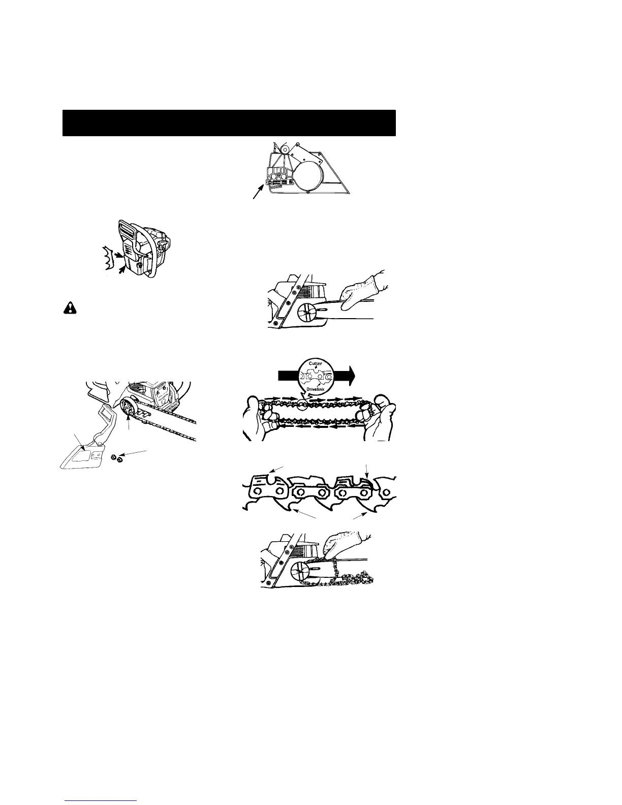
ATTACHING THE BUMPER SPIKE
The bumper spike may be used as a pivot
when making a cut.
1. Loosen and remove the chain brake nuts
and the chain brake from the saw.
2. Attach the bumper spike with the two
screws as illustrated.
ATTACHING THE BAR & CHAIN (If
not already attached)
WARNING: Recheck each assem-
bly step if the saw is received assembled. Al-
ways wear gloves when handling the chain.
The chain is sharp and can cut you even
when it is not moving!
1. Loosen and remove the chain brake nuts
and the chain brake from the saw.
2. Remove the plastic shipping spacer (if
present).
Chain
Brake
Chain Brake
Nuts
Clutch Drum
3. An adjusting pin and screw is used to ad-
just the tension of the chain. It is very im-
portant when assembling the bar , that the
pin located on the adjusting screw aligns
into a hole in the bar . Tu rning the screw will
move the adjustment pin up and down the
screw. Locate this adjustment before you
begin mounting the bar onto the saw . See
illustration below.
Adjustment located on Chain Brake
Inside view of
Chain Brake
4. Turn the adjusting screw by hand coun-
terclockwise until the adjusting pin just
touches the stop. This should allow the
pin to be near the correct position.
5. Slide guide bar behind clutch drum until
guide bar stops against clutch drum
sprocket .
Mount the Bar
6. Carefully remove the chain from the pack-
age. Hold chain with the drive links as
sho wn .
CUTTERS MUST FACE IN
DIIRECTION OF ROT ATION
Tip of
Bar
Cutters
Depth Gauge
Drive Links
Placechainontothes