Jotron AS| TR7750C: Operators Manual Installation
P/N: 84748 (G)
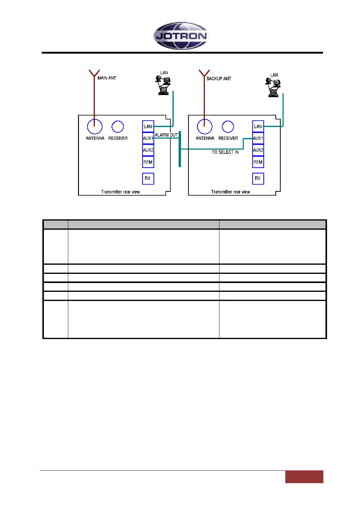
Figure 4.7-4, Main / Backup transmitter
Connect the alarm_out signal (p.1,2) from AUX1 on the main
transmitter to the select_in signal (p.3.6) on AUX1 on the standby
transmitter. The connection can be done via a distribution panel or
by making a special with RJ45 connectors in each end. The cables
used should be of the same quality as a CAT5E network cable and
the screen should be connected in the plugs.
Set Alarm config, Alarm pin pullup to Enabled (default)
5.5.3 – Interface config group
Set Alarm config, Select polarity to Low (default)
5.5.3 – Interface config group
Set the main transmitter Operation mode to Main
5.5.1 – Radio control group
Set the backup transmitter Operation mode to Norm (default)
5.5.1 – Radio control group
Connect separate antennas to the two transmitters.
Alternatively use an external antenna change over unit (ACU) in
order to switch the antenna between the main and standby
transmitters. The antenna change over unit can be controlled by
the alarm signal on the main unit
Table 4.7-4, Main/backup configuration, transmitters

 Loading...