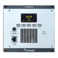
Jotron AS| TR7750C: Operators Manual Functional description
P/N: 84748 (G)
3.4.5 AUX2 connector (RJ45)
This connector is normally connected to equipment used for remote control / remote supervision of
the transmitter.
AUX2 connector, receiver unit
Closed=Receiving (Sq open), optocoupler output
Closed=Receiving (Sq open), optocoupler output
Hi/Lo output depending on signal strength,
optocoupler output
Hi/Lo output depending on signal strength
AGC analogue voltage output, depending on signal
strength. Referred to GND
Table 3.4-3, AUX2 connector, receiver, pin out
3.4.6 REM connector (RJ45)
This connector is normally connected to a mating transmitter unit (RX connector) when used in a
transceiver configuration, or to other equipment used for remote control of the receiver.
When connected to a transmitter, the connector gives “transceiver” functionality to the transmitter
and contains necessary signals for audio and control. The TX_BUSY and RX_BUSY signals are also used
in data modes to signal that the transmitter or receiver is busy transferring data.
Interface to Remote equipment or a transmitter unit
Line output from Receiver unit, 600 ohm
TX Busy indicator input (Mute input)
Line output from Receiver unit, 600 ohm
Low=Alarm (Note: I/O – low input will also be
recognized as an alarm (EXT))
Table 3.4-4, REM connector, receiver, pin out
 Loading...