JOTRON electronics a.s.
December, 99
Page 16
❺
SELECT switch.
The SELECT switch increments or decrements the channel, or frequency according to
the position of the FUNCTION switch.
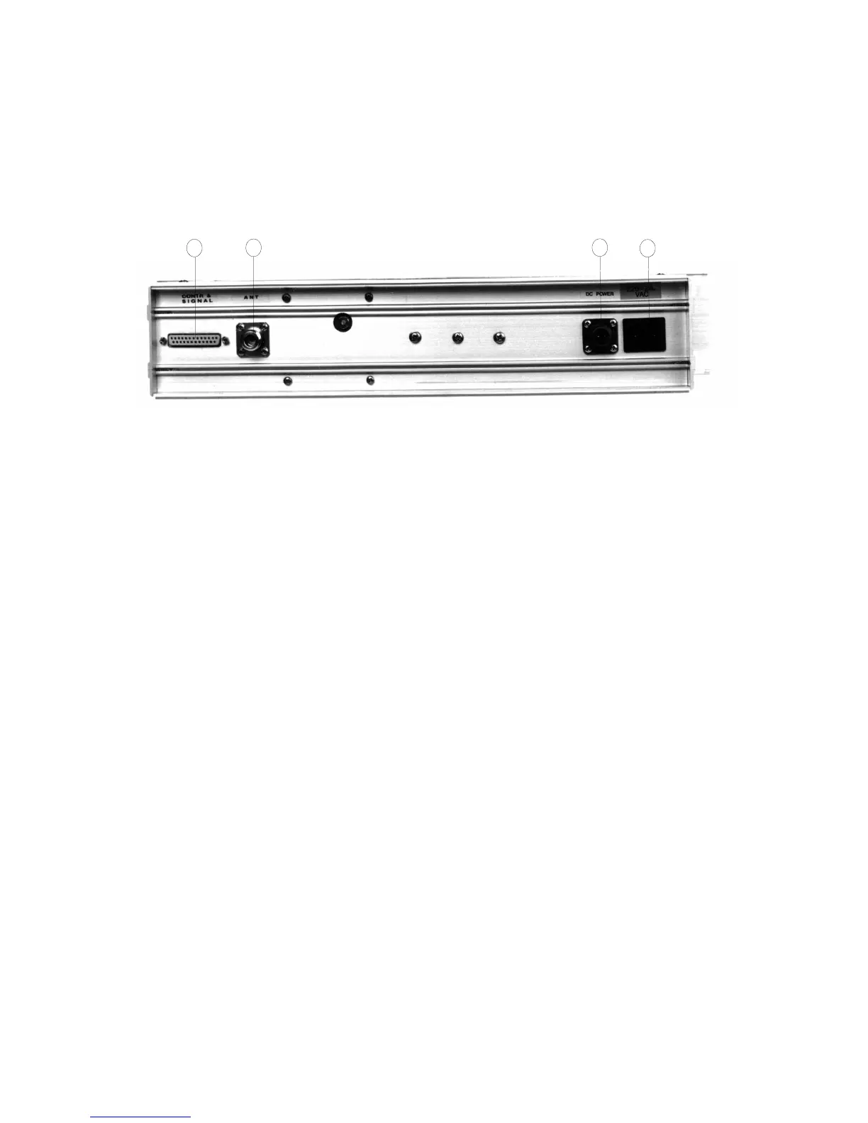
2.2. Rear panel connections
2
1
3
4
➀
➀➀
➀
Antenna connector (N-type)
The antenna connector should be connected to a 50 antenna.
The VSWR of the antenna must be less than 3:1, preferable less than 2:1 for a well
performing system.
➁
REMOTE CONNECTOR (25 pin D-SUB)
The remote connector contains the necessary signals for interfacing the radio to
remote equipment. The connector has the following pin configuration.
PIN NO
1 SIDETONE OUTPUT
The sidetone output is a high impedance output which can be used to
monitor the transmitted audio. The signal is the AC component of the
demodulated signal when the transceiver is keyed.
2 REMOTE KEY DC INPUT
The remote key in is used to key the transceiver in the remote position.
The key signal must be a DC voltage between 5 and 30V referred to
GND (pin 14). The transceiver is keyed when the DC voltage is applied.
3/4 600 LINE INPUT/OUTPUT
The 600 line contains the received audio in receive mode and the audio
to be transmitted in transmit mode. The transceiver must be in REMOTE
position to use the line.
The transceiver can also be keyed with this line by using line loop keying
(making a DC path between the two lines).