14 92478_UM_ SART_ F
3
FUNCTIONAL DESCRIPTION
3.1
GENERAL
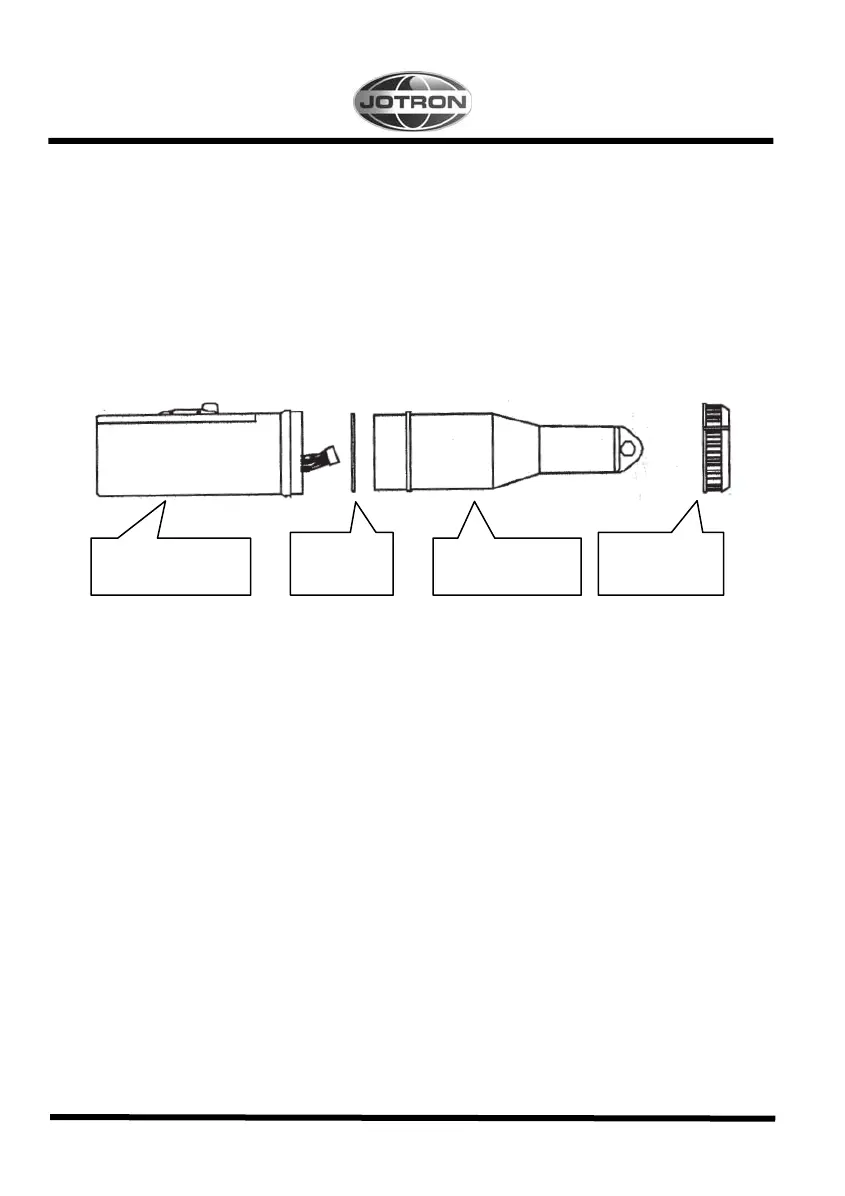
The Tron SART consists of upper and lower house mounted together with an O- ring and screw ring.
Tron SART may be split into the following main parts:
1. Upper module with transponder and antenna
2. Battery module with batteries, main switch, LED indicator and buzzer.
3. O- ring and screw ring.
Figure 3.1, Tron SART disconnected
3.1.1
Upper module with transponder and antenna
The Upper module consists of one printed circuit boards, a VCO and antenna, which are mounted in the
upper housing:
1.
The main board.
2.
VCO.
3. Antenna (9GHz).
The housing is made of polycarbonate.
3.1.2
Battery module
The battery module consists of the complete lower half of the Tron SART and is to be replaced every
4. year. The marking on the battery unit show the expire date.
A new battery module comes complete with switch and indicators and is easily replaced by opening the
screw ring between the top and bottom of the SART.
3.1.3
O-ring and screw ring
The two parts of the housing are put together with the O-ring gasket, and is locked with a screw ring.
Battery module
-
Upper module
-
O-ring
X-90624
Screw ring
X-90641

 Loading...