5
• Provide protection from dust and water
• Not exceed the allowed operation temperature (40°C of the
regulator and 60°C throttle)
• Guarantee air exchange inside the casing
• Prevent from accessing hazardous parts
• Electrical installation, which the regulator is connected to,
should be equipped with a device enabling to disconnect
both supply poles according to regulations applying to
construction of such installations.
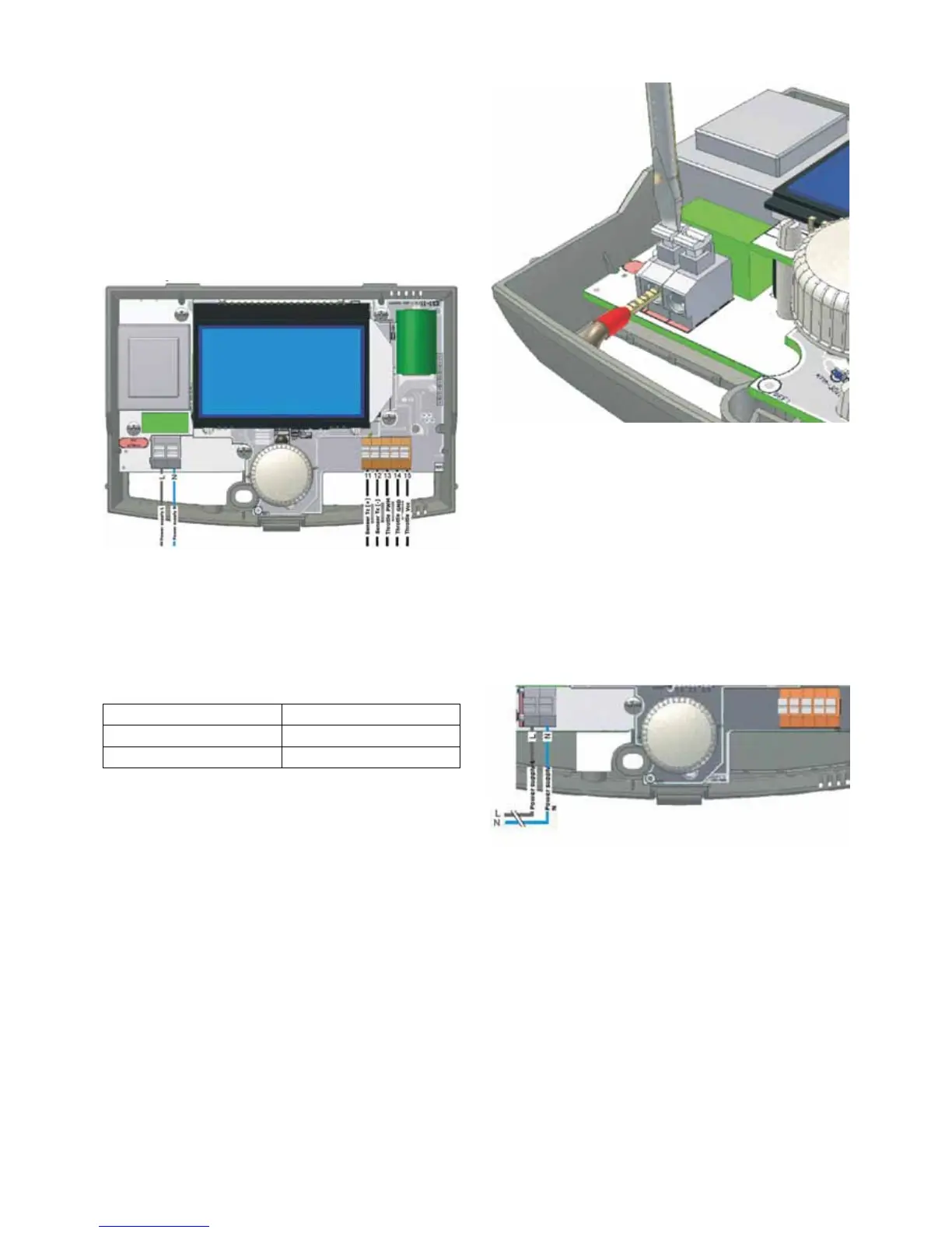
4.2 Connecting external circuits
Fig. 04 Regulator interior with terminals
4.2.1 Handling terminals
The regulator is equipped with clamping terminals with springs
which are purposed for connecting cables with bushing tips.
The range of allowable cross section areas of cables connected
to terminals are shown in a table below:
Circuit type Network circuits
Low-voltage circuits 0.75÷1 mm
2
*
Low-voltage circuits 0.25÷0.75 mm
2
*For installation with a wire cable, the maximum cable cross
section is 1.5 mm
2
In order to provide appropriate cooperation of the cable with
a terminal, the length of not insulated ending of the cable and
bushing tip should be within the range of 8÷10 mm.
Cable is inserted into a terminal by pushing a button on this
terminal with a flat screwdriver, inserting the cable tip (with a
collet) and releasing the button.
Fig. 05 Handling clamping terminals
4.2.2 Connecting network circuits
Important! The device should be installed when the power
supply is disconnected.
The regulator is adapted for power supply of 230V~, 50Hz.
Supply is connected to terminals marked with „->”, „L” and „N”.
Power cables for supplying 230V network devices should
be routed in such a way as to prevent their contact with
cables connected with sensors and other low-voltage units;
additionally, each cable cannot be in contact with surfaces
with temperature exceeding nominal operation temperature of
these cables
Fig. 06 Connecting power supply
4.2.3 Temperature sensor installation
The ERS 01 regulator cooperates with K-type thermocouples.
Measurement range of supplied exhaust gases sensor is
50÷1150°C; the sensor should be installed on a flue where the
exhaust gasses come out of the fireplace. The opening for
inserting a sensor should be 6mm in diameter. Active length of
a sensor cover is 70mm.
Supplied sensor is equipped with a 2m cable.
 Loading...