AG-5 series
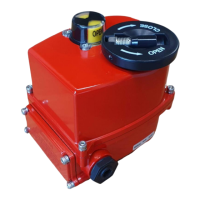
Electric actuator
6
AG-5 series actuator www.jpfluidcontrol.com
Feedback (optional)
Always apply a load (max. 5A) in the feedback circuit to prevent permanent damage. Always apply
the correct polarity/phasing. The limit switches share a common source, do not use different power
supplies on both limit switches at the same time. Terminal 7, 8, 9 & 10 must have the exact same
polarity, voltage & frequency when both are being used.
AG-550-A/B: The position of the limit switches can be measured by the terminal pairs 8&10 (closed) and/or
9&10 (open).
Limit switch closed position (pair 7&10): Connect terminal 7 to a signal indicator that is connected to a
load and connect terminal 10 to the same load.
Limit switch open position (pair 9&10): Connect terminal 9 to a signal indicator that is connected to a
load and connect terminal 10 to the same load
In order for the mechanical indicator the show the correct position of the valve, the actuator
and the valve have to be aligned. Hence, both should be either in the open or in the closed
position.
Align the position of the valve and the actuator. That is, open or close both the actuator and the valve
The actuator may be installed in any position, but it is recommended to install the actuator in a
vertical position, with the position indicator facing upwards. This reduces the probability of moisture
entering the actuator. When the electric ball valve is mounted at an angle, it is recommended to
deviate maximally 90° from the vertical position. Ensure that drops cannot slip along the cable and
enter the actuator. See figure 8 for a visual explanation.
The actuator can be mounted to valves with a flange according to ISO 5211 type F03, F05 or F07.
For valves with a shaft of 9x9mm or 11x11mm, an enclosed adapter can be used. The valve must be
fixed to the actuator by four bolts of M5 (type F03), M6 (type F05) or M8 (type F07).
Mount the actuator to the valves with the appropriate flange.
Play between actuator and valve may damage the valve or the actuator and/or reduce its
performance.
Remount the Terminal Block chamber cover and the housing cover with the Captive Bolts (figure 3).
Figure 8: Mounting angle actuator and ISO 5211 mounting flange.
 Loading...