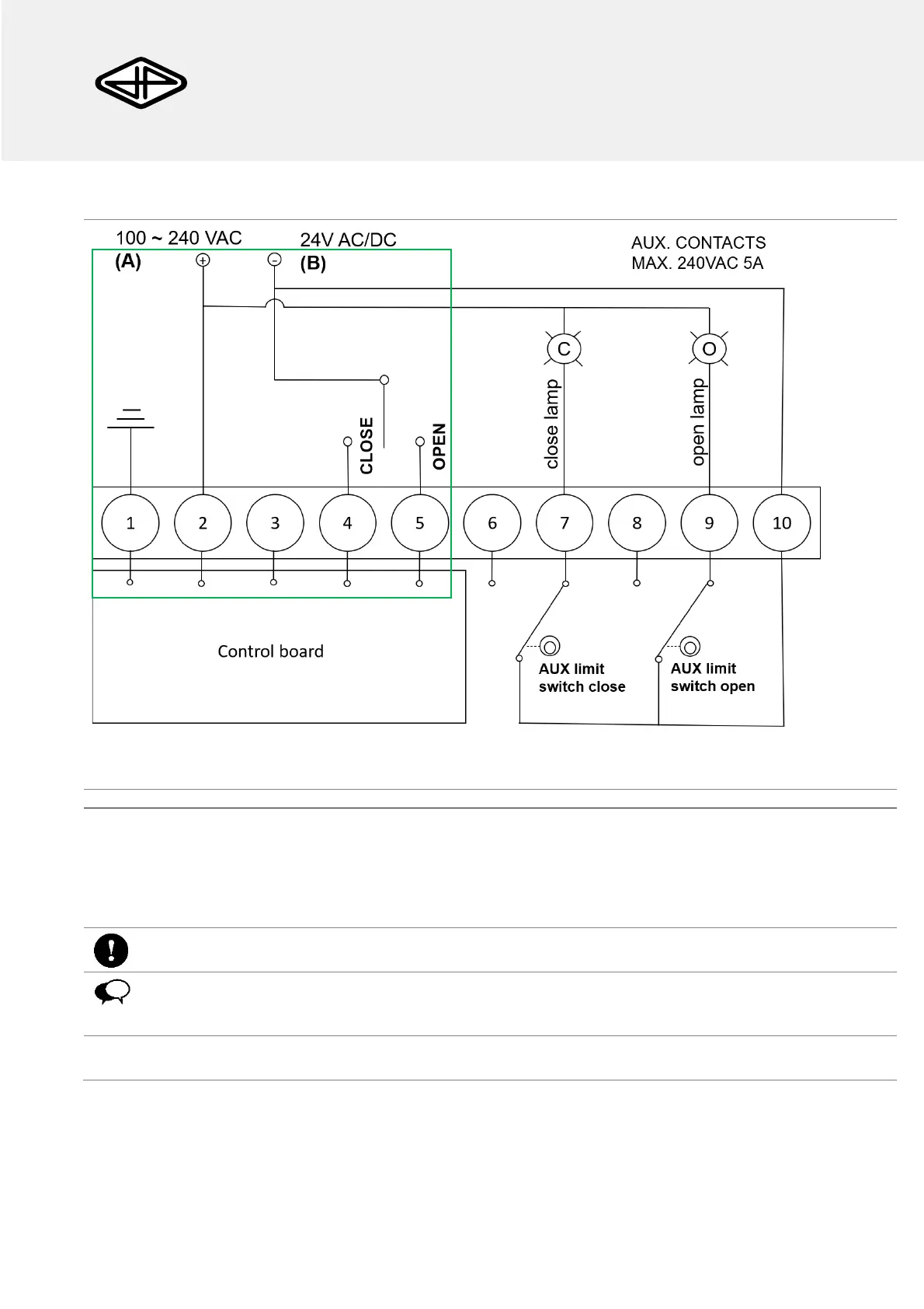
EasyManua.ls Logo

JP AG Series - Electrical Wiring; Grounding Electrical Equipment

JP AG Series
8 pages
Print Icon
To Next Page IconTo Next Page
To Previous Page IconTo Previous Page
Loading...
JP FLUID CONTROL
AG-5 series
Electric actuator
5
AG-5 series actuator www.jpfluidcontrol.com
Electrical wiring
Figure 5: Wiring diagram (3 point connection) for the AG-550 models. The minimally required wiring for operation is
shown in the green box.
6
AG 550 A (100-240VAC): Connect terminal 2 to the power supply, connecting terminal 4 to the
power supply closes the actuator, connecting terminal 5 to the power supply opens the actuator.
AG 550 B (24V AC/DC): Connect terminal 2 to the positive terminal of the power supply.
Connecting terminal 4 to the negative terminal of the power supply closes the actuator, connecting
terminal 5 to the negative terminal of the power supply opens the actuator.
Never use the piping to ground the electrical equipment.
Always connect the ground, which is provided with a residual current device at voltages above 50 volts.
7
Connect the ground to terminal 1 (Figure 5a & b).