AG-5 series
Electric actuator
4
AG-5 series actuator www.jpfluidcontrol.com
Step-by-step installation guide
Do not use sharp objects while opening the box. Make sure the actuator is disconnected from
any electricity before following the installation guide.
Carefully open and unpack the box.
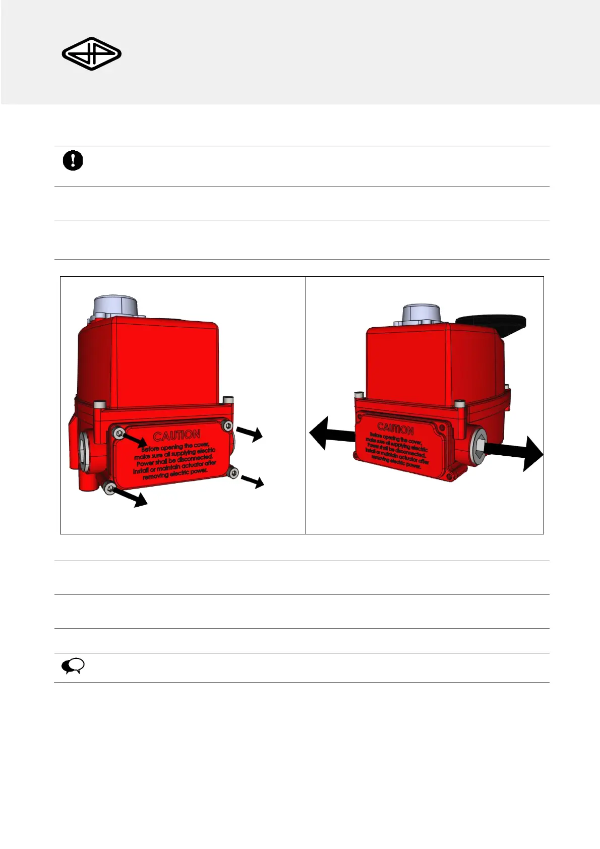
Loosen the four Captive Bolts of the Terminal Block chamber (Figure 3) and the four captive bolts of
the housing cover (Figure 4).
Figure 3: Captive bolts to remove.
Figure 4: Removing the cable glands.
Remove the terminal block chamber cover, the housing cover and the cable glands.
Insert a suitable cable through the Cable Gland.
Remove the terminal block from the Terminal block chamber.
The wires should be connected to the terminal block (Figure 1), according to the wiring
diagram (Figure 5 a/b).