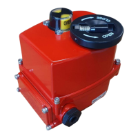
AG-5 series
Electric actuator
8
AG-5 series actuator www.jpfluidcontrol.com
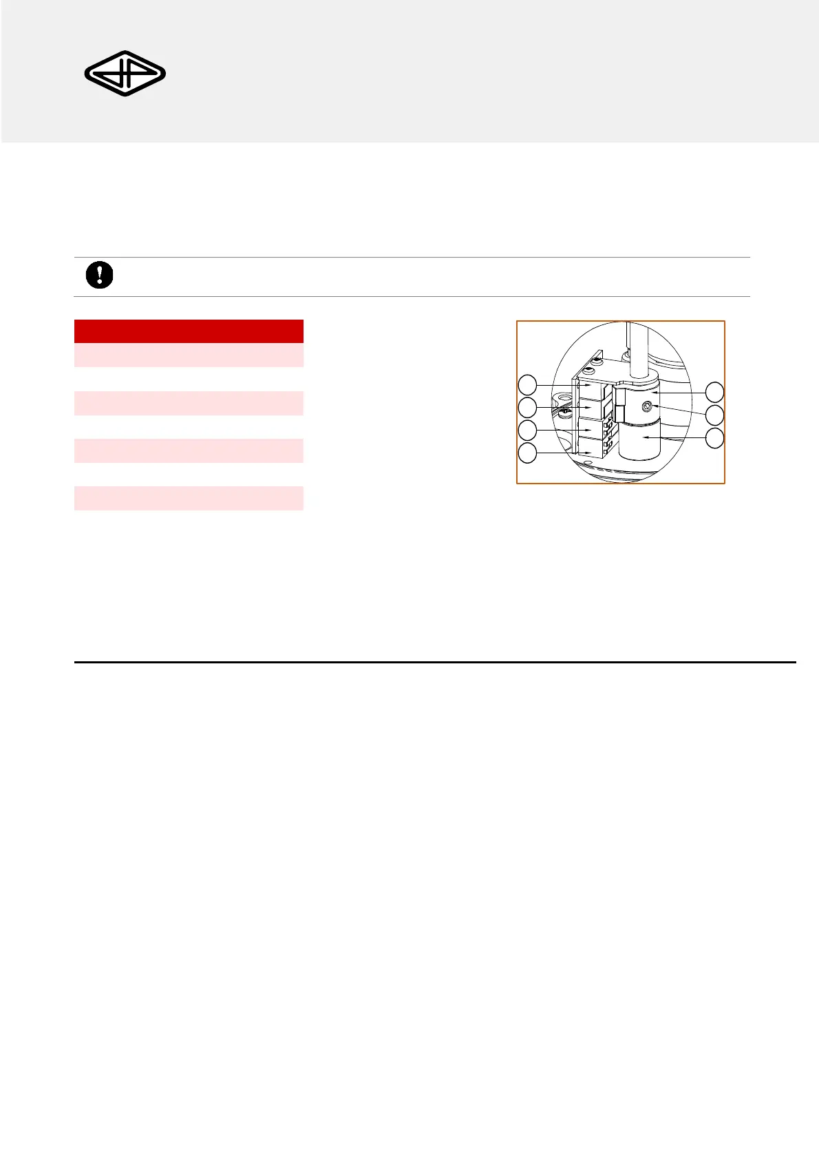
Limit Switch Adjustment
The limit switch cams can be adjusted to the desired angle. The standard setting is such that ball valves are
fully closed or fully opened. For special applications the cam position may be altered by loosen the locking bolt
(6), adjusting the cam to the right angle and locking the locking bolt again.
The angle may be altered only for a few (<10) degrees since the actuator has a limited range.
Disposal
The removal of the product should be performed in accordance with the applicable laws. Keep in mind the
media that are still present in the valve.
This manual can be downloaded from www.jpfluidcontrol.com. Modifications reserved. This document has been prepared with
great care. JP Fluid Control assumes no responsibility for any errors that may appear in this document. No rights can be derived
from this document.
Auxiliary Close Limit Switch
Auxiliary Open Limit Switch
Figure 10: Limit Switch Adjustment.