1 – 26
1
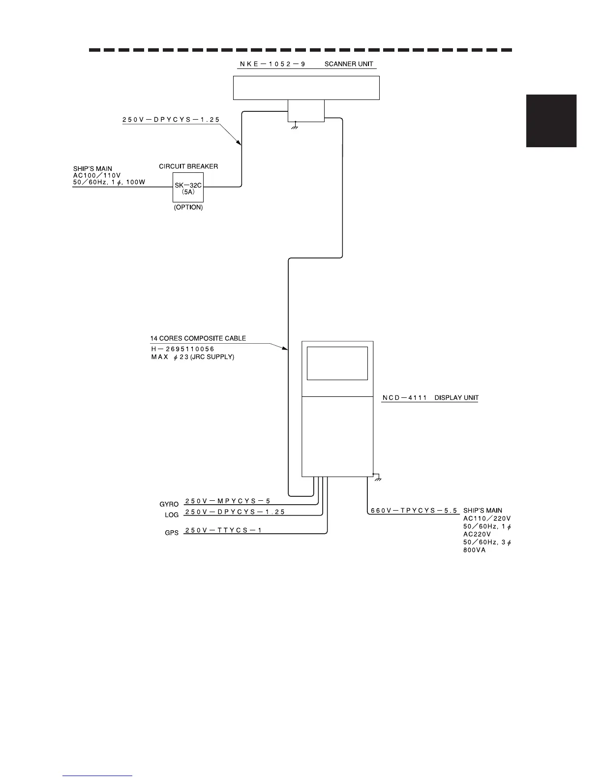
1.5 GENERAL SYSTEM DIAGRAM
.
Note: Eliminating the interference on frequencies used for marine communications and
navigation due to operation of the radar.
All cables of the radar are to be run away from the cables of radio equipment.
(Ex. Radiotelephone. Communications receiver and dirrection finder. etc.)
Especially inter-wiring cables between scanner unit and display unit of the radar
should not be run parallel with the cables of radio equipment.
Fig.1.18 GENERAL SYSTEM DIAGRAM OF
RADAR, TYPE JMA-9822-9XA
 Loading...


