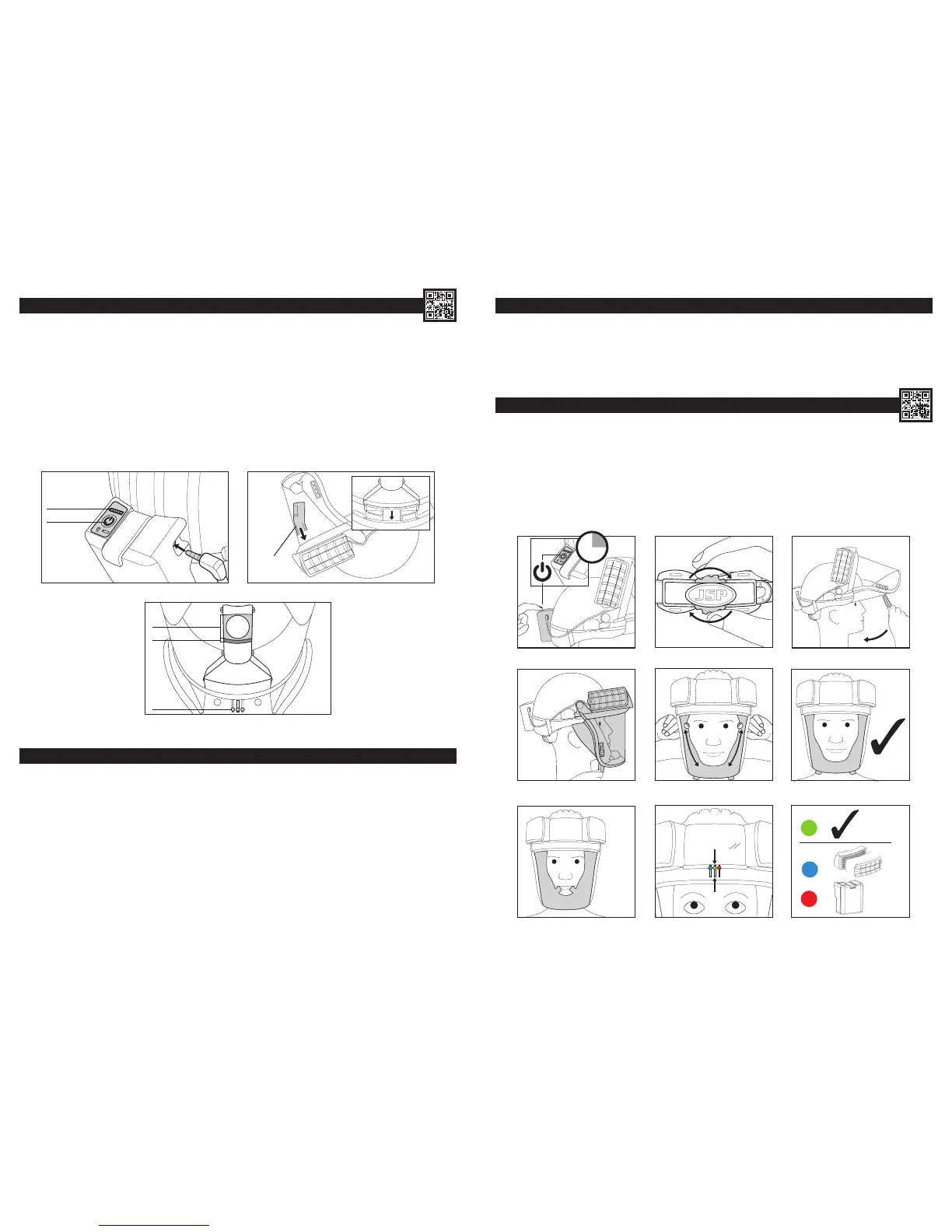
BATTERY & AIRFLOW CHECK: (The lters must be tted)
1. Checking the battery. Insert the male power cable connector into the battery pack. Check the charge level by momentarily pushing
the switch on the battery pack.The 5 LEDs represent 100-80%, 80-60%, 60-40%, 40-20%, 20-0%. Turn the unit on by pushing and holding the
switch on the battery pack. The adjacent LED charge level indicator will light momentarily. Airow will commence. The drive unit warning buzzer
will sound momentarily. The Heads-Up Display (HUD) in the visor will ash through its start-up sequence.
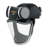
2. Checking the airow. (Always check the airow level before use using the airow indicator provided). Invert the PowerCap
®
Innity
®
so it is
resting on the helmet and the two lters. Fit the airow indicator supplied over the air outlet inside the rim of the visor carrier ensuring a good seal.
3. Avoid placing hands or other possible obstructions over the lter inlets. The ball indicator within the airow device should move fully into the
“green zone” which means that there is adequate airow for PowerCap
®
Innity
®
to be used. The ball indicator in the green zone will be accompanied
by a green HUD light. Insufcient ow will be indicated by the ball being all or partly in the “red zone”. If the ow test unit and/or HUD lights indicate
insufcient ow: Check the battery tting and connection and check the charge condition. Check the lter and pre-lter condition (See Removing
& Replacing Filters and Removing & Replacing Pre-Filters sections). In the event that there is still insufcient airow, do not use the product, but
contact JSP Ltd for further advice. The HUD lights should always be the primary method of assessing ow levels.
1
POWER
CHARGE LEVEL
AIRFLOW
INDICATOR
2
GREEN ZONE
RED ZONE
HUD LIGHTS
3
6
GENERAL USE & WARNING SYSTEM:
• PowerCap
®
Innity
®
will deliver a minimum 160L/min of ltered air to the user for upwards of 8 hours through a fresh pair of lters.
• The user may notice changes in motor tone associated with movement, this is a normal operational sound linked to motor construction.
• The array of LEDs at the top of the eld of vision is a Head-Up Display (HUD) informing the user of PowerCap
®
Innity
®
’s status.
• As the battery approaches low remaining charge, the green light will be joined by a ashing red light to inform the user of having approximately 20
minutes to withdraw from the hazard area to replace/recharge the battery.
• As the battery approaches a fully discharged state, the green light will extinguish and the ashing red light will be joined by a two-tone buzzer. The
user should withdraw from the hazard zone immediately to replace/recharge the battery pack.
• Do not use or store PowerCap
®
Innity
®
at temperatures below +5°C as the battery performance can be affected.
• When the green light is replaced by a blue ashing light and a pulsed buzzer tone, the system is no longer able to deliver sufcient airow as the
lters are too blocked. The user should withdraw from the hazard zone immediately to check and/or replace both lters.
• PowerCap
®
Innity
®
is rated as IP54 for protection against water and dust ingress. The unit can be used in dusty environments and in the rain. It
should not be immersed in water.
DONNING: (DO NOT enter the hazard zone until you have fully donned the product)
1. Turn PowerCap
®
Innity
®
on with a long press of the switch on the battery box. Wait for the drive unit buzzer to signal that it has started.
Sufcient airow must be checked as described in the Battery and Airow Check section.
2. Place the helmet on the head, pressing the head rmly into the padding at the front of the helmet. Tighten the helmet strap by turning the wheel
ratchet at the rear of the helmet clock-wise. Adjust for a comfortable, secure t.
3. Pull the seal skirt and visor assembly down so the seal skirt is fully underneath the jaw.
4. Locate the two tabs on the seal skirt with the index ngers uppermost and thumbs underneath.
5. Peel the sides of the skirt outwards with the index ngers to fully seal around the face.
6. Check for the green indicator on the Head-Up Display (HUD). When correctly donned, no part of the faceskirt should be in front of the face.
Check by looking in a mirror or seek assistance.
USING POWERCAP
®
INFINITY
®
:
• Operating temperature should be between +5°C and +40°C and relative humidity not greater than 75%.
• PowerCap
®
Innity
®
offers protection against non-toxic bres, fumes and dusts.
• The visor offers protection against medium energy impacts, short circuit electric arcs, molten metals and hot solids to EN166.
• The EVO5
®
helmet offers protection against falling objects to EN397.
2
3
1
2
sec
5
4
6
=
=
=
7