TAB
8 9
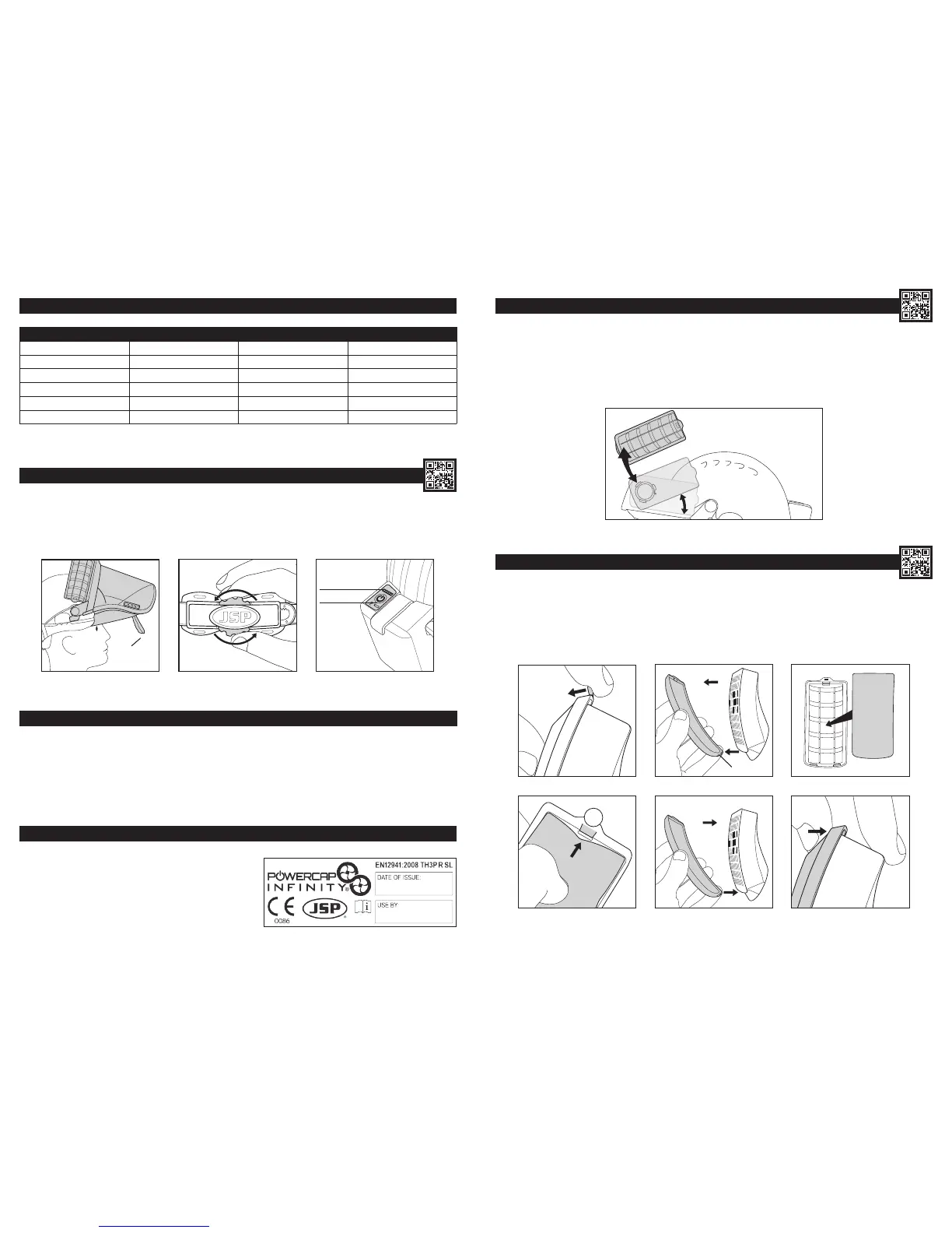
REMOVING & REPLACING FILTERS:
To Remove the Filters: Rotate the rear of each lter upwards by 30° until resistance is encountered, then pull away from the motor housing.
To Replace the Filters: Ensure that the lter and motor housing mating faces are clean; do not allow any dust or foreign objects to fall into the motor
housing. Press and twist the replacement lters into place until a click is heard/felt. Recheck airow before use. (See Battery and Airow Check).
If the lters are not tted correctly, ltering efciency will be severely reduced. Each lter is tted with a pre-lter housed within a protective cover.
Pre-lters prolong the life of the main lters by trapping larger particles. The pre-lters can be replaced from within the protective covers as needed.
Dispose of used lters in accordance with local legislation.
REMOVING & REPLACING PRE-FILTERS: (Always replace both pre-lters simultaneously)
1. Locate the tab at the rear of the pre-lter cover and lift it to begin freeing the cover.
2. Release the two remaining hooks from under the front of the main lter case lid to release the cover from the main lter body.
3. Pull the pre-lter out from under the three locating hooks. Dispose of used pre-lters in accordance with local legislation.
4. Clean the pre-lter cover using a damp cloth and/or soft brush, then feed a fresh pre-lter underneath the three locating hooks.
5. Clip the pre-lter cover back onto the lter, locating the curved front edge rst.
6. Snap the rear clip into place over the rear of the lter case lid.
1 2 3
1
4 5
6
HOOKS
PRE-FILTER
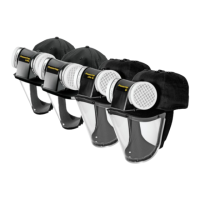
FILTERS:
• The lters provided are high efciency particulate types supplied in pairs.
• They will lter most particulate matter such as dust, spores, mist and fumes.
• They will not lter gases, vapours or toxic substances.
• PowerCap
®
Innity
®
lters are marked as per right image.
Only use genuine PowerCap
®
Innity
®
lters supplied in pairs from
JSP Ltd or its distributors. Always replace both lters simultaneously.
NEVER use compressed air on the lters. This will seriously limit protection.
WARNING SCENARIO TABLE:
SCENARIO DISPLAY BUZZER COMMENTS
Start up Red, green, blue On (2s) System OK
Standard running Green static Off System OK
Draining battery Green (Red ash every 2s) Off 20 minutes remaining
Flat battery Red ash High-low tone Recharge battery
Blocked lters Blue ash High pulsed Change BOTH lters
Other fault Red, blue (repeat) High pulsed Contact JSP Ltd
3
DOFFING: (DO NOT remove the product whilst in the hazard zone)
1. Pull the tabs on the seal-skirt outwards and upwards to raise the visor.
2. Turn the red wheel anti-clockwise to loosen the helmet. Lift the assembly off the head.
3. Press and hold the power button on the battery pack to switch off. The adjacent battery charge level indicator will light momentarily to display the
remaining charge level.
POWER
CHARGE LEVEL
1 2
30°
MAINTENANCE:
It is important to follow the following instructions to ensure that the PowerCap
®
Innity
®
gives optimal performance. Regular maintenance is important. If
the maintenance and usage instructions in this leaet are not followed, the effectiveness and the protection offered by the PowerCap
®
Innity
®
may be
severely reduced. A radio frequency identication (RFID) device has been built in to PowerCap
®
Innity
®
so that your maintenance records can be kept
using JSP’s Asset Management system. This allows you to have full control over your PowerCap
®
Innity
®
giving full access in the eld to inspection
dates, compliance documentation, product instructions and much more. Visit www.jspcheck.com to enable your RFID device.