– 6 –
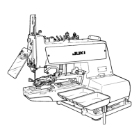
3-10.
Adjustment of the button clamp stop lever
When clamp screw
1
is loosened in the state of
stop-motion, button clamp jaw levers
3
opens/clos-
es w
ith button clamp stop lever
2
. Set a button to
the correct position and x button clamp stop lever
2
at the pos
ition where taking in and out of the but-
ton
is easily performed with clamp screw
1
.
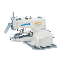
3-7.
Position of the needle guide
Loosen screw
2
and provide a 0.05 to 0.1 mm clear-
ance between the needle gu
ide
1
and the needle
by moving the needle guide
1
to the left or the r
ight
when the needle is in the lowest position.
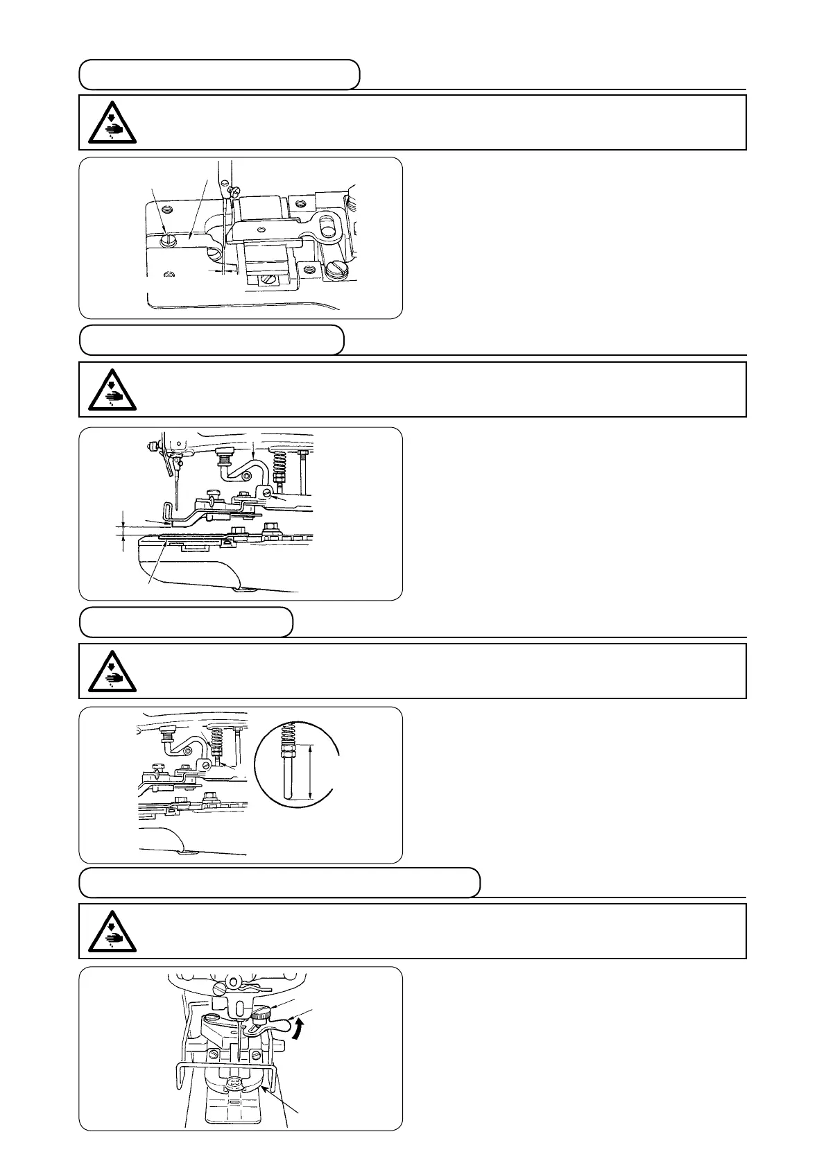
3-8. Height of the button clamp
1) The standard clearance
A
between the rear s
ide
of the bottom face of button clamp jaw lever
1
and the top surface of feed plate
2
is 8 mm at
the position where the machine has stopped after
sewing.
2) To adjust the height of the button clamp unit,
loosen screw
3
in the button clamp lifting hook
and move button clamp lifting hook
4
up or
down.
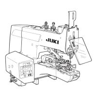
3-9. Work pressing force
The standard work pressing force is by providing a
28.5 to 29.5 mm between the top end of nut
1
and
the bottom end of pressure adjusting bar
2
.
Turn nut
1
to adjust
it.
WARNING :
To protect against possible personal injury due to abrupt start of the machine, be sure to start the
following work after turning the power off and ascertaining that the motor is at rest.
WARNING :
To protect against possible personal injury due to abrupt start of the machine, be sure to start the
following work after turning the power off and ascertaining that the motor is at rest.
WARNING :
To protect against possible personal injury due to abrupt start of the machine, be sure to start the
following work after turning the power off and ascertaining that the motor is at rest.
WARNING :
To protect against possible personal injury due to abrupt start of the machine, be sure to start the
following work after turning the power off and ascertaining that the motor is at rest.
1
2
3
4
3
2
1
A
28.5 to
29.5 mm
2
1
1
2
0.05 to 0.1 mm