– 10 –
12.Knee lifter lever
Preparation
™ Remove outer components.
(Excluding belt cover and motor cover)
™ Raise presser foot.
Disassembly
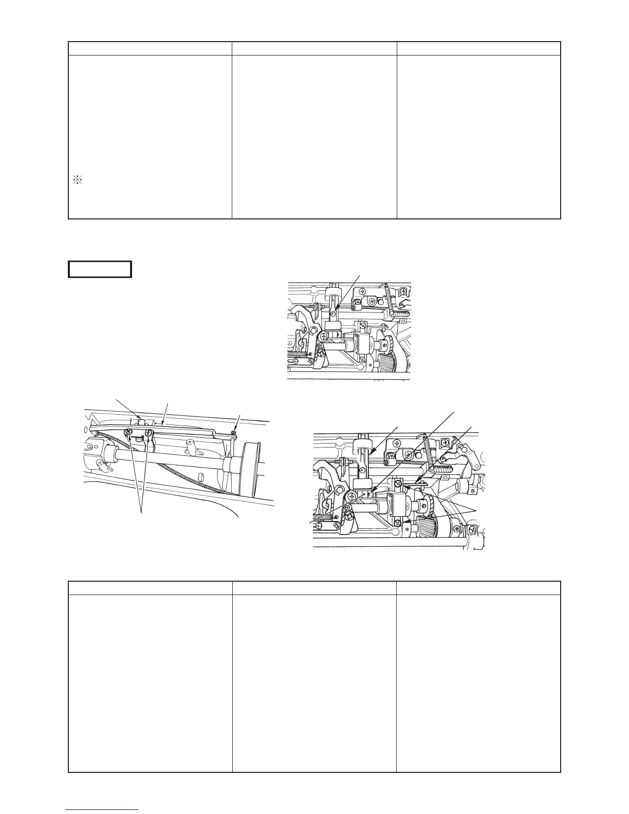
™ Remove snap 4 pin.
™ Remove 5 setscrews and
remove 6.
™ Remove 1 setscrew and take out
lever spring.
™ Lower 2 and turn it to the position
where 3 can be removed.
™ Remove 3, remove claw lever
actuating plate, and draw out 2.
™ Remove claw lever shaft 7
setscrew.
™ Remove 8 link asm..
Assembly
™ Attach 8 to frame and tighten 7
setscrews.
™ Set 2 lever shaft, attach 9 claw
lever actuating plate and tighten
it with 3.
™ Attach lever spring and tighten
with 1.
™ Raise frame, attach 6 knee lifter
lever to knee lifter lever !0 shaft,
and tighten it with 5.
™ Enter 4 snap pin.
Point
™ There should not be a play in the
axial direction of 2 knee lifter
lever shaft.
Disassembly
™ Remove 1 nut (left side only).
™ Remove 2 setscrew and remove
tube presser.
™ Remove 3 setscrews and
remove wire holder mas. asm.
™ Remove setscrew in thread
release 6 plate shaft and remove
thread release 4 plate.
When removing the wire from
frame, make sure of wire route in
frame.
Assembly
™ Lay wire in frame.
™ Connect thread release 4 plate
with disk pressure release
connecting 5 link.
™ Assemble wire holder mas. asm.
and tighten with 3 setscrews.
™ Fix 2 and 1 in the reverse side
of machine bed.
Point
™ Pass the wire through full reverse
side of stitch dial.
™ Contact 4 and 5 with each other.
™ For 2, tube has to come out by
13 mm from tube presser.
™ Tube presser and tube regarding
2 should be on the same face.
See item 5 on page 27 for 1.
2 Knee lifter lever shaft
8 Knee lifter link asm
(claw lever plate)
7 Claw lever shaft
setscrew
SM5041255SN
3 Claw lever actuating plate
setscrew SM8040602TP
6 Knee lifter lever
5 Knee lifter lever shaft stop
plate setscrew
SM5040855SN
4 Knee lifter link snap pin
1 Knee lifter lever shaft spring setscrew
SM5030455SF
!0 Knee lifter
lever shaft
9 Claw lever
actuating
plate
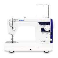
TL-98Q
 Loading...