Do you have a question about the JUMO AQUIS 500 AS and is the answer not in the manual?
Symbol used when there may be danger to personnel if instructions are ignored.
Symbol used to draw special attention to a remark.
Describes the device's analog inputs, binary input, and general capabilities.
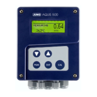
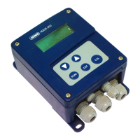
Lists the main features of the device, such as display, visualization, and enclosure protection.
Details the information found on the device's nameplate.
Explains the structure of the order code and its components.
Provides general advice on mounting location and installation position.
Details the steps for mounting the device on a surface.
Outlines the steps for panel mounting the device, including cut-out details.
Provides safety instructions and general guidelines for electrical connections.
Step-by-step guide on how to open and close the device enclosure.
Shows the terminal layout for connecting wires.
Details the pin assignments for various connections like supply voltage, inputs, and outputs.
Identifies and describes the device's buttons and their functions.
Provides a comprehensive overview of configurable parameters and their organization.
Details how to use manual mode with higher-order control functions.
Explains how to access the administrator level and its capabilities.
Provides a step-by-step guide for initial device setup and configuration.
Provides practical examples for common measurement setups.
Details the requirements and steps for zero point calibration.
Explains the requirements and process for two-point calibration.
Explains requirements and process for two-point calibration of pH electrodes.
Explains requirements and process for two-point calibration of redox electrodes.
Details requirements and steps for calibrating the relative cell constant.
Explains requirements and process for linear temperature coefficient calibration.
Describes the function and purpose of the setup program and PC interface cable.
Lists technical specifications for analog inputs.
General electrical specifications of the device.
Lists parameters configurable at the operator level with their ranges.
Defines terms like Pulse Width Controller, Pulse Frequency Controller, and Calibration Timer.
Provides dimensions and instructions for the panel cut-out.
| Protection Class | IP65 |
|---|---|
| Display | LCD |
| Inputs | Up to 4 inputs |
| Outputs | Up to 4 relay outputs |
| Communication | Modbus RTU |
| Measured Variables | temperature |
| Dimensions | 96 x 96 x 108 mm |