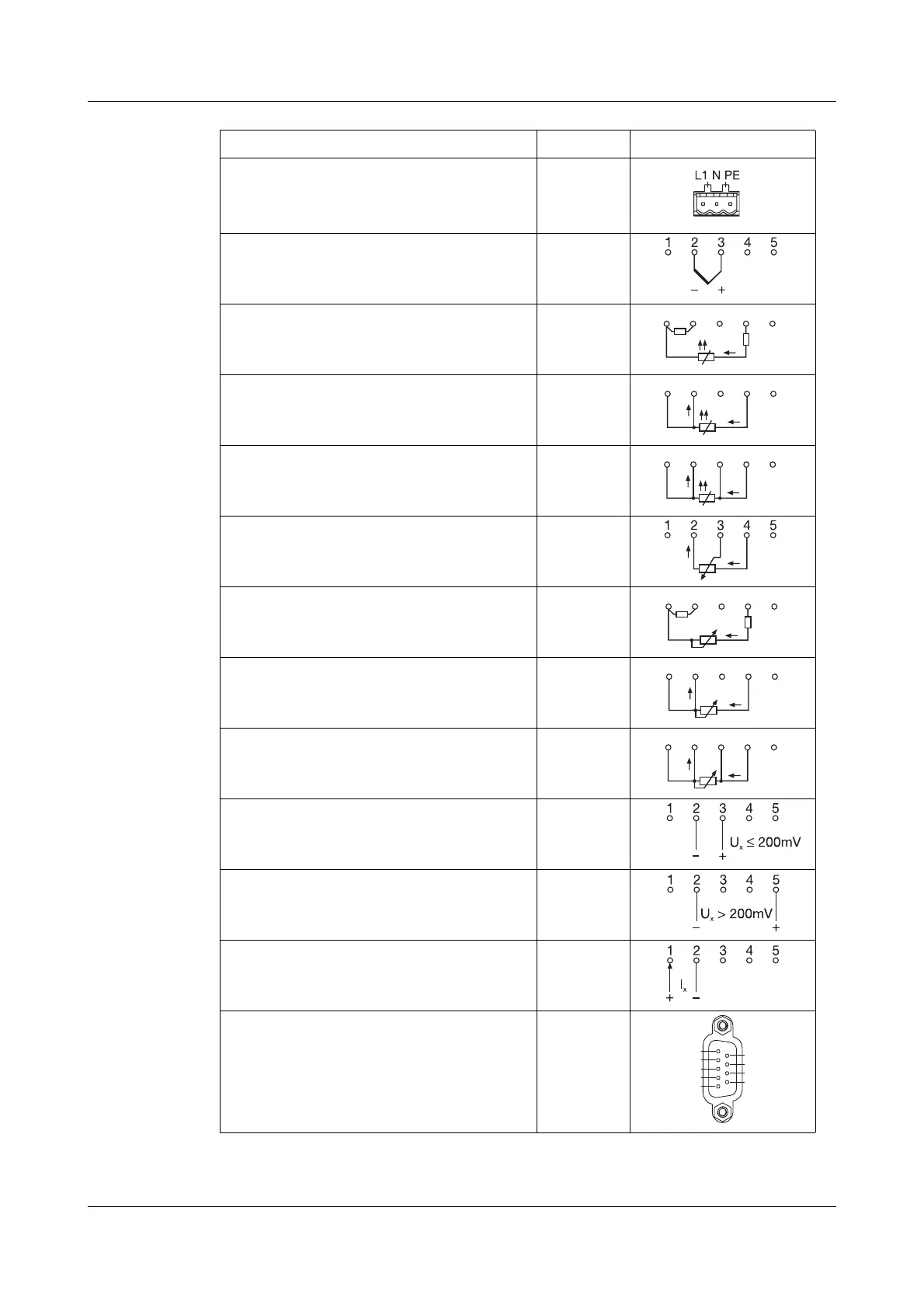
4 Electrical connection
18
Terminal assignment
Connector
Connection diagram
Supply Supply voltage
as per data sheet
L1(L+)
N (L-)
PE
Analog
inputs
Thermocouple 1 to 12
Resistance thermometer
in 2-wire circuit
1 to 12
Resistance thermometer
in 3-wire circuit
1 to 12
Resistance thermometer
in 4-wire circuit
1 to 12
Resistance transmitter 1 to 12
Potentiometer in 2-wire circuit 1 to 12
Potentiometer in 3-wire circuit 1 to 12
Potentiometer in 4-wire circuit 1 to 12
Voltage input ≤ 200mV 1 to 12
Voltage input > 200mV 1 to 12
Current input 1 to 12
Interfaces RS232C 9-pole SUB-D socket
2 RxD receive data
3 TxD transmit data
5 GND ground
20
R
L
R
A
R=R
AL
21 345
21 345
21 345
R
L
R
A
R=R
AL
21 345
21 345
21 345
2
1
3
4
5
6
7
8
9
 Loading...