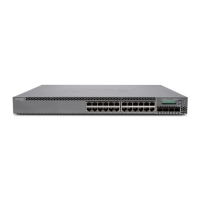
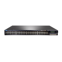
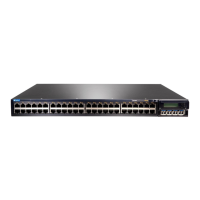
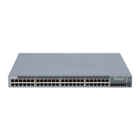
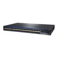
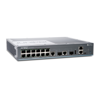
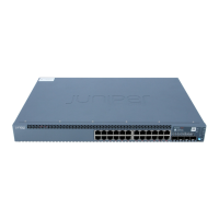
EX3400 Switch Quick Start
See the complete EX Series documentation at
http://www.juniper.net/documentation/.
To mount the Juniper Networks EX3400 Ethernet Switch on
two posts of a rack, you need:
z Two mounting brackets and eight mounting screws
(provided)
z Screws to secure the chassis to the rack (not provided)
z Phillips (+) screwdriver, number 2 (not provided)
To connect the switch to earth ground, you need a
grounding cable (minimum 14 AWG [2 mm²], minimum 90°C
wire) with a grounding lug (Panduit LCC10-14BWL or
equivalent) attached, a pair of 10-32x0.25-in. screws with #10 split-lock washer, and a
pair of #10 flat washers—none provided.
To connect AC power to the switch, you need a power cord with a plug appropriate for
your geographical location (provided) and a power cord retainer strip (provided).
To connect DC power to the switch, you need a terminal connector (provided), DC power
cables (14–16 AWG) (not provided) with wire pins (Molex 192120005) attached (not
provided) and a slotted (-) screwdriver (not provided).
To perform initial configuration of the switch, you need:
z Ethernet cable with an RJ-45 connector attached (provided)
z RJ-45 to DB-9 serial port adapter (provided)
z Management host, such as a laptop or PC, with an Ethernet port (not provided)
Register product serial numbers on the Juniper Networks website and update the
installation base data if there is any addition or change to the installation base or if the
installation base is moved. Juniper Networks will not be held accountable for not meeting
the hardware replacement service-level agreement for products that do not have
registered serial numbers or accurate installation base data.
Register your product(s) at https://tools.juniper.net/svcreg/SRegSerialNum.jsp.
Update your install base at
https://www.juniper.net/customers/csc/management/updateinstallbase.jsp.
The fan modules and the power supplies in EX3400 switches are hot-removable and
hot-insertable field-replaceable units (FRUs) installed in the rear panel of the switch: You
can replace them without powering off the switch or disrupting switch functions.
CAUTION: Do not mix power supplies and fan modules with different airflow labels
(AIR IN [AFI] and AIR OUT [AFO]) in the same chassis.
WARNING: Ensure that you understand how to prevent electrostatic discharge
(ESD) damage. Attach the ESD grounding strap to your bare wrist, and connect the
strap to the ESD point on the chassis.
Part 1: Mount the Switch on Two Posts of a Rack
You can mount an EX3400 switch on a desk or a level surface, on two or four posts of a
rack or cabinet, or on a wall. This guide describes the procedure to mount the switch on
two posts of a rack.
Mounting an EX3400 switch on a rack requires one person to lift the switch and a second
person to install the mounting screws.
1. Place the rack in its permanent location, allowing adequate clearance for airflow and
maintenance, and secure it to the building structure.
NOTE: When you mount multiple units on a rack, mount the heaviest unit at the bottom
and mount the other units from bottom to top in decreasing order of weight.
2. Align the mounting brackets along the front of the side panels of the chassis.
3. Attach the brackets to the chassis by using the mounting screws. Tighten the screws.
4. Have one person grasp both sides of the switch, lift the switch, and position it in the
rack, aligning the mounting bracket holes with the threaded holes in the rack rail.
Align the bottom hole in each mounting bracket with a hole in each rail, making sure
that the chassis is level.
5. Have the second person secure the switch to the rack by using the appropriate
screws. Tighten the screws.
Part 2: Connect Power to the Switch
NOTE: Grounding is required for DC systems and recommended for AC systems. An
AC-powered switch gets additional grounding when you plug the power supply in the
switch into a grounded AC power outlet by using the power cord.
To connect earth ground to a switch:
CAUTION: A licensed electrician must attach the lug to the grounding cable.
1. Secure the grounding lug on the grounding cable to the earthing terminal on the rear
panel by using washers and screws.
2. Connect the other end of the grounding cable to a proper earth ground.
To connect power to an AC-powered switch:
The power cord inlet is on the power supply installed in the switch.
1. Push the end of the power cord retainer strip into the slot above the power cord inlet
until the strip snaps into place. Ensure that the loop in the retainer strip faces toward
the power cord.
2. Press the small tab on the retainer strip to loosen the loop. Slide the loop until you
have enough space to insert the power cord coupler into the power cord inlet.
3. Insert the power cord coupler firmly into the power cord inlet.
4. Slide the loop toward the power supply until it is snug against the base of the coupler.
5. Press the tab on the loop and draw out the loop into a tight circle.
6. If the power source outlet has a power switch, set it to the off (0) position.
7. Insert the power cord plug into the power source outlet.
8. If the power source outlet has a power switch, set it to the on (|) position.
9. Verify that the AC OK and the DC OK LEDs are lit green and on steadily.
To connect power to a DC-powered switch:
The DC power inlet on the power supply installed in the switch has terminals labeled +
and –.





 Loading...