Getting Started Guide
SRX650 Services Gateway
PART 1 - CONNECTING AND CONFIGURING THE DEVICE
Use the instructions below to connect and set up the SRX650 Services Gateway to protect your network. Refer to the
LEDs on the front and back panels of the device to help you determine the status of the device.
Overview:
The SRX650 Services Gateway is a security device that requires these
basic configuration settings to function properly.
• Interfaces must be assigned IP addresses.
• Interfaces must be bound to zones.
• Policies must be configured between zones to permit/deny traffic.
• Source NAT rules must be set.
Factory-default settings:
Security policies:
NAT rule:
Step 1
Connect the power cable to the device and a power source. We
recommend using a surge protector. Note the following indications:
• POWER LEDs (solid green) on front and back panels: The device
is receiving power.
• STATUS LED (solid green) on back panel: The device is
operating normally.
• ALARM LED (amber) on front panel: The device is operating
normally in the absence of rescue configuration. This is not a panic
condition.
Note: A solid red ALARM LED indicates a major problem exists on the
services gateway.
Important: You must allow the services gateway between five and seven
minutes to boot up after you have powered it on. Please wait until the
STATUS LED is solid green before proceeding to the next step.
Step 2
Connect the management device to the services gateway using either of
the following methods:
• Connect an Ethernet cable from the ge-0/0/1 port to the Ethernet
port on the management device (workstation or laptop). We
recommend this connection method.
If you are using this method, proceed with Step 3.
Interface Security Zone DHCP State IP Address
ge-0/0/0 untrust client 0.0.0.0
ge-0/0/1 trust server 192.168.1.1/24
ge-0/0/2 trust server 192.168.2.1/24
ge-0/0/3 trust server 192.168.3.1/24
Source Zone Destination Zone Policy Action
trust untrust permit
trust trust permit
untrust trust deny
Source Zone Destination Zone Policy Action
trust untrust source NAT to untrust zone interface
Use the instructions in this guide to help you connect the SRX650 Services Gateway to your network. For details, see the
SRX650 Services Gateway Hardware Guide at http://www.juniper.net/techpubs/a065.html.
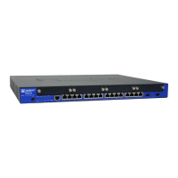
Front Panel
Back Panel
1. Mounting brackets
2. ALARM LED
3. FAN LED
4. SRE/ACE LED 1.0
5. ESD outlet
6. 10/100/1000 Ethernet ports
7. GPIM/XPIM slots
8. POWER LED
9. HA SYS LED
10. SRE/ACE LED 0 (Applies to SRE modules only)
11. SRE/ACE LED 1.1
12. Power button
g032700-gsg
1
2
3
4
5
8
9
10
11
12
6
7
1. Power supply slots
2. Multi-use processing
slot
3. Services and Routing
Engine (SRE) slot 0
(shown with SRE module
installed)
4. Fan tray
5. Air filter
(behind fan tray)
6. Reset Config
7. SRE LEDs
8. AUX port
9. Console port
10. External CompactFlash
slot
11. USB ports (2 each)
DC OK AC OK
SRE 6
Services and Routing Engine 6
OFFLINE RESET
CONFIG
ALARM POWER STATUS
AUX CONSOLE
HA
SRE
CF ACT
COMPACT FLASH
USB 0 USB 1
g032703
1
3
4
5
7
8 9
11
6
10
2