INSTALLATION, USE AND MAINTENANCE MANUAL – LC
Jurop SpA
Via Crosera n° 50
33082 Azzano Decimo, PN (Italia)
TEL. +39 0434 636811 FAX. +39 0434 636812
http://www.jurop.it
e-mail: info@jurop.it
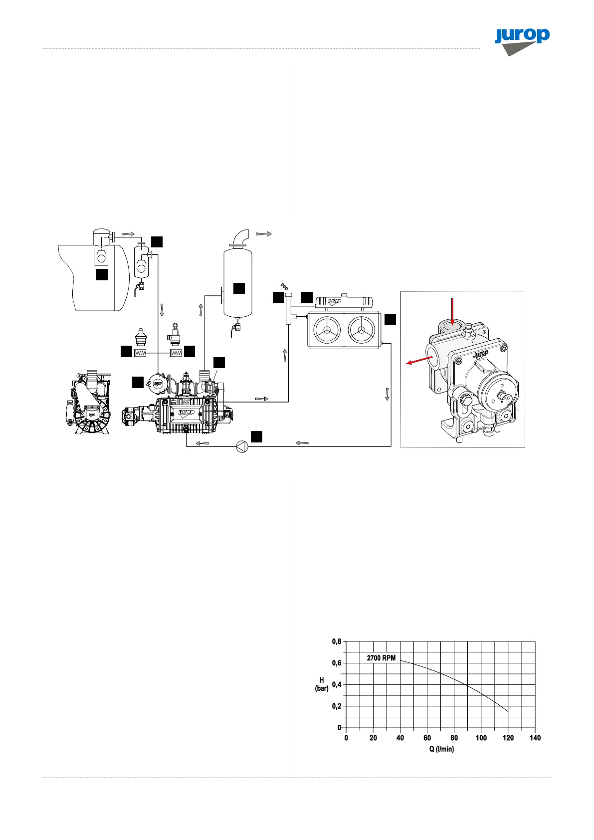
4.5. Vacuum - pressure line
• To avoid accidental suction of liquids inside the pump, install a
primary (pos. 1) and a secondary flow shutoffs (pos. 2). If necessary,
install also a suction filter (pos. 4) to protect from solids infiltration.
• The exhaust silencer (pos. 6) is designed to reduce the noise level
and to separate the oil mist coming out from the pump outlet port. The
separator must be periodically drained from oil and condensate
accumulated in the separator during the normal pump functioning.
• The diameter of the vacuum/pressure line pipes must be properly
dimensioned to the pump flow and, in any case, larger than the
diameter of the ports.
• The pipes weight must not solicit the body of the pump. Use high
temperature resistant rubber connections.
• Before mounting the vacuum line to the pump, remove the port
protections. Pipes and all line components must be clean.
• Avoid restrictions and tight curves as much as possible if not
strictly necessary.
• Exhaust pipes can reach high temperatures. Hence, they must be
properly isolated.
Pic. 4.2
Overpressure safety valve
• Safety valves:
− Overpressure safety valve (pos. 5): mount it close to the pump.
The valve flow must prevent the LC pump from exceeding the
absolute pressure of 2.0 bars or the maximum pressure allowed by
the system. Do not apply gate valves on the line;
− Vacuum control valve (pos. 6): install if necessary to limit the
vacuum rate of the system.
4.6. Cooling system
• Please follow the outline on figure 4.2 to make the connection.
• The cooling system is composed of:
− Centrifugal recycle pump;
− Heat exchanger with electric fans operated by a thermostat;
− Expansion tank with an atmospheric pressure vent system.
• The heat exchanger must dissipate the heat power indicated in
par. 2.3. The Fig. 4.3 shows the characteristic curve “Flow – Head” of
the recycle pump.
• The circuit shall be vented to ambient pressure.
• Fill the system by venting any air pockets.
• The cooling liquid temperature must not exceed 60° C. The airflow
generated by the exchanger fans must be kept free of obstacles.
• We recommend using a mixture of water and glycol (min 30%) as
coolant and, in any case, in percentage compatible with the expected
minimum temperatures to which the system will be subjected.
• In the event of draining and replacing the coolant, dispose of it
according to the regulations in force.
Pic. 4.3
CIRCULATING PUMP
(Figure shows: water pump left)