INSTALLATION, USE AND MAINTENANCE MANUAL – LC
Jurop SpA
Via Crosera n° 50
33082 Azzano Decimo, PN (Italia)
TEL. +39 0434 636811 FAX. +39 0434 636812
http://www.jurop.it
e-mail: info@jurop.it
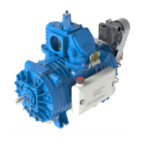
• The following figure shows a possible schematic view of a correct
hydraulic connection.
Pic. 4.6
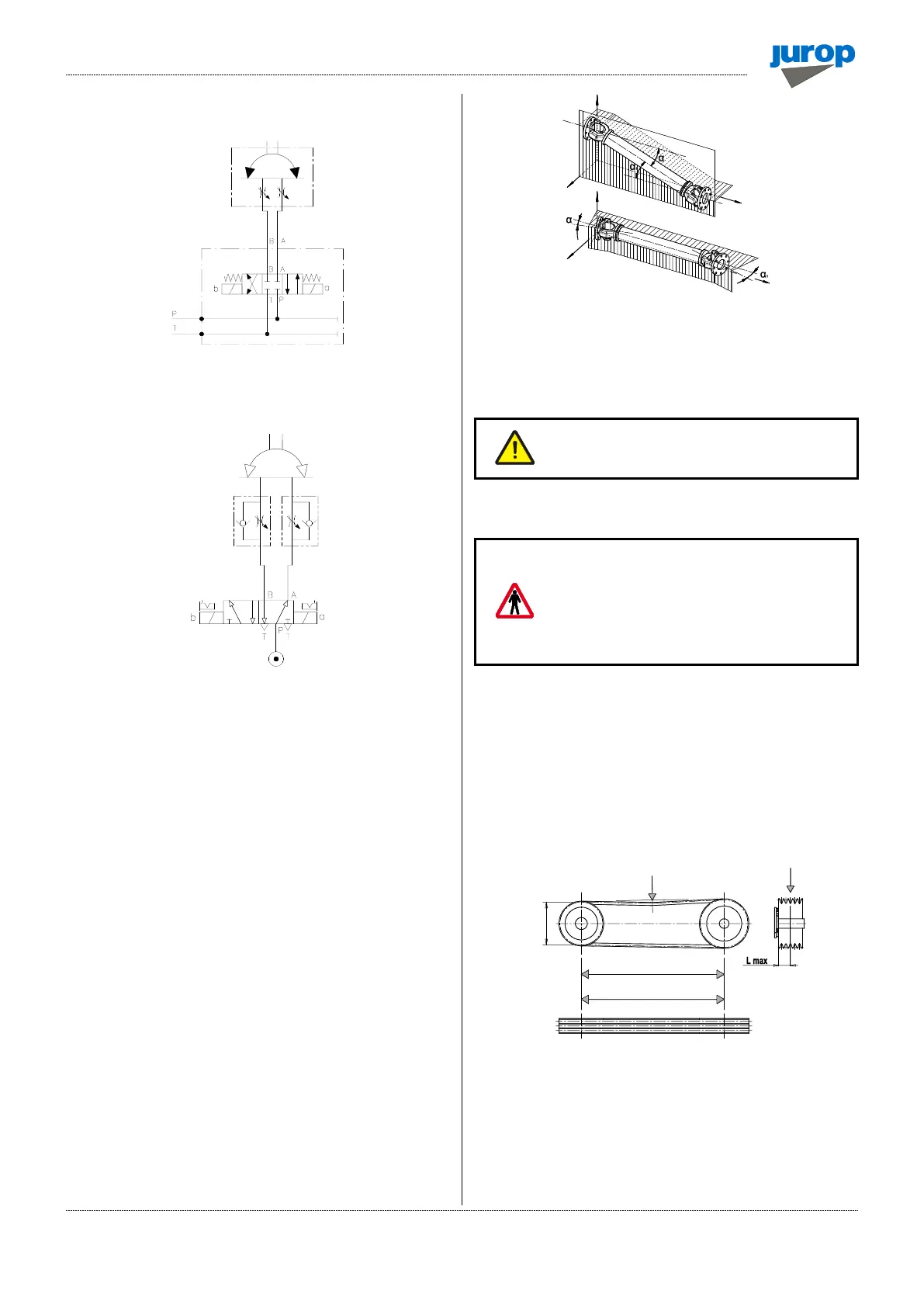
• The following figure shows a possible schematic view of a
pneumatic connection.
Pic. 4.7
• In case of interruption of the pneumatic or hydraulic supply, the
inverter of the suction unit remains in the same position it was when the
failure occurred.
4.9. Pump mounting - Drive connection
• For the machines of this series, the allowed power transmissions
are:
− Direct transmission (e.g.: from agricultural cardan shaft);
− Oil hydraulic transmission (e.g.: hydraulic motor).
• Protect with a fixed or interlocked guard and signal with
pictograms the power transmission chosen and applied by the final
installer, if there is the possibility that the operator will come into
contact during handling.
A) Cardan shaft drive
• Use telescopic cardan shafts.
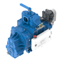
• In order to achieve a uniform motion of the driven shaft, the
following requirements must be met (see Fig. 4.6):
− Equal working angle α and α1 of both couplings.
− The internal fork joints must be coplanar.
− Both driven and driving shafts must be coplanar.
Pic. 4.8
• It is also recommended working with limited articulated joint angles
(max 15° at 1000 rpm and max 11° at 1300 rpm) and disengaging the
transmission for those operations requiring great angles (steering or
lifting).
Follow the rotation direction as indicated on the
front flange. Follow the instructions of the cardan
shaft’s manufacturer.
• Use the cardan guard supplied with the pump, by fixing it to the
pump itself.
Use the cardan guard supplied with the pump, by
fixing it to the pump itself. In any case, the
installation, by the final installer, must comply
with the current EC accident prevention
regulations and must be compatible with the
geometry of the protection cap supplied with the
machine.
• The protection must not be removed; in case of removal, it is the
responsibility of the final installer to provide for suitable guards
according to the assembly.
• It is the responsibility of the final installer to provide for suitable
guards, in presence of transmission shafts exposed during normal
operation.
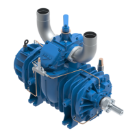
B) Belt drive
Pic.4.9
• Install a suitable pulley on the smooth shaft as close as possible to
the pump: max 35 mm.
• Apply an adequate belt tension (see manufacturer’s data). Max
3000N.
• Do not use driven or driving pulleys with a pitch diameter inferior
to 180 mm. Small pulleys require a high belt tension which may cause
premature wear to the bearing or transmission troubleshooting.
ALINGN PULLEY GROVES
AND BELTS