INSTALLATION, USE AND MAINTENANCE MANUAL – LC
Jurop SpA
Via Crosera n° 50
33082 Azzano Decimo, PN (Italia)
TEL. +39 0434 636811 FAX. +39 0434 636812
http://www.jurop.it
e-mail: info@jurop.it
4.7. Overheating alarm (optional)
• The vacuum pump can be equipped at the request of thermostat
sensor.
• Overheating alarm is strongly recommended in the following
cases:
− Operations close to the use limits.
− Under pressure operations.
− Not well defined or monitored operation conditions.
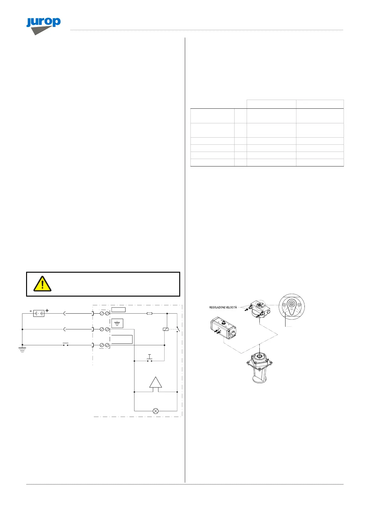
• The alarm (available upon request) is composed of a blinking light
and a warning buzzer that have to be connected to the thermostat
(sensor). It is available at 12V or 24V.
• Consider the thermostat characteristics (See Fig. 4.4).
− Voltage from 6V to 24V with CC, from 6V to 12V with AC.
− Maximum power: 3W.
• When threshold temperature is reached the alarm system is
enabled and a gate valve (along vacuum line) is opened.
• It has to be mounted in a protected position in order to keep it free
from water and other damaging media. Prepare the necessary
connections for the electrical feeding.
• If the box supplied as an accessory is not used, make a check
circuit as illustrated in Fig. 4.4.
• Overheating can seize the vacuum pump, causing a damage also
in the drive line. Stop the pump for cooling or drive it at free ports
conditions (with the suction valves fully opened) to let it cool down
properly. The pump can be again operated only when the alarm is
turned off after cooling.
• Check the muffler cleanliness. Obstructions may cause
overheating.
Attention: overheating can seize the vacuum
pump, causing a damage also in the drive line.
Pic. 4.4
4.8. Vacuum-pressure inverter: remote control
actuators
• A specific design of the vacuum-pressure diverter available on
request enables the application of a pneumatic or hydraulic angular
actuator (90°).
• See the exploded view at the end of the manual for spare parts.
Filtered, dried compressed
air
ISO 8573-1 classe 4
(15 micron)
Hydraulic actuator installation
• Adjust movement speed using the two built-in valves.
• Use a closed-centre distributor or apply a block valve.
Pneumatic actuator installation
• Adjust movement speed by applying two unidirectional flow control
valves.
For both actuators
• Adjust speed: full rotation should not take less than 1 second.
• Fluid filtration: ensure a level equal to or greater than the
recommended value.
• In the event of a (hydraulic or pneumatic) supply failure, the
suction unit inverter will remain in the same position it was when the
failure occurred.
Pic. 4.5
Maintenance
• The diverter is adjusted before shipment and does not usually
require further adjustments.
• Diverter lubrication:
− Use NLGI 2 Lithium grease. Quantity: 80-100 grams for 1000
working cycles.
− A bleeder hole covered by a filter is preventing the hole to overfill.
Clean the filter whenever clogged.
• Hydraulic actuator: the control valves are equipped with an internal
metal filter. Disassemble and clean if movement stops.
• Pneumatic actuator: for non-dried air, use temperature 0 ÷ +80°C.
OVERHEATING
WARNING DEVICE
INDICATOR POSITION
(ACTUATOR AT END OF STROKE)