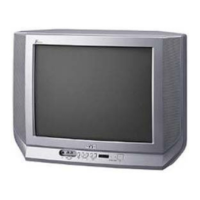
No. 52024
V-21F3
V-21FR3
V-21FMG3B
16
BASIC OPERATION OF SERVICE MENU
"
The adjustment using SERVICE MENU
The f ollowing adjus tment it ems u se t he SE RV ICE MENU in the ser ies of the adju stment . The ad ju stment s ar e m ade on the bas is of the
initial se tting valu es. Th e ad justment valu es which ad ju st t he screen to th e o ptimum co ndit ion c an b e diffe re nt from th e in itia l sett ing va lues.
With th e S ERVICE ME NU, var ious s ett in gs c an be made , and they ar e br oa dly classifie d in the f ollo win g ite ms of s ettin gs.
1.I F ・・・・・・・ ・・・・・・・・・・・・・・・・ Adjustment of th e IF circuits.
2.V /C ・・・・・・・ ・・・・・・・・・・・・・ ・・ Ad ju stmen t of the VIDEO /CHRO MA circuit.
3.DEF ・・・・・・・・・・・・・・・・・・・・ ・ Adjustment of the DEFLECTION circ uit.
4.V SM PRES ET ・・・・・・・ ・・・・・ Ad ju stmen t of th e init ia l sett in g value s of VSM co nd it ion as STA NDARD, SOFT a nd BRIGHT.
(VSM : Video Status Memory)
5.PRESET
・・・・・・・ ・・・・・・・・・・
Adju stmen t of th e RF circ uit [Do not adjust].
6.SETUP TOUR OFF ・・・・・・・・ It s hou ld b e able to select mode ( LANGUAG E a nd AUTO CH PRESE T).
[Shou ld be OFF].
"
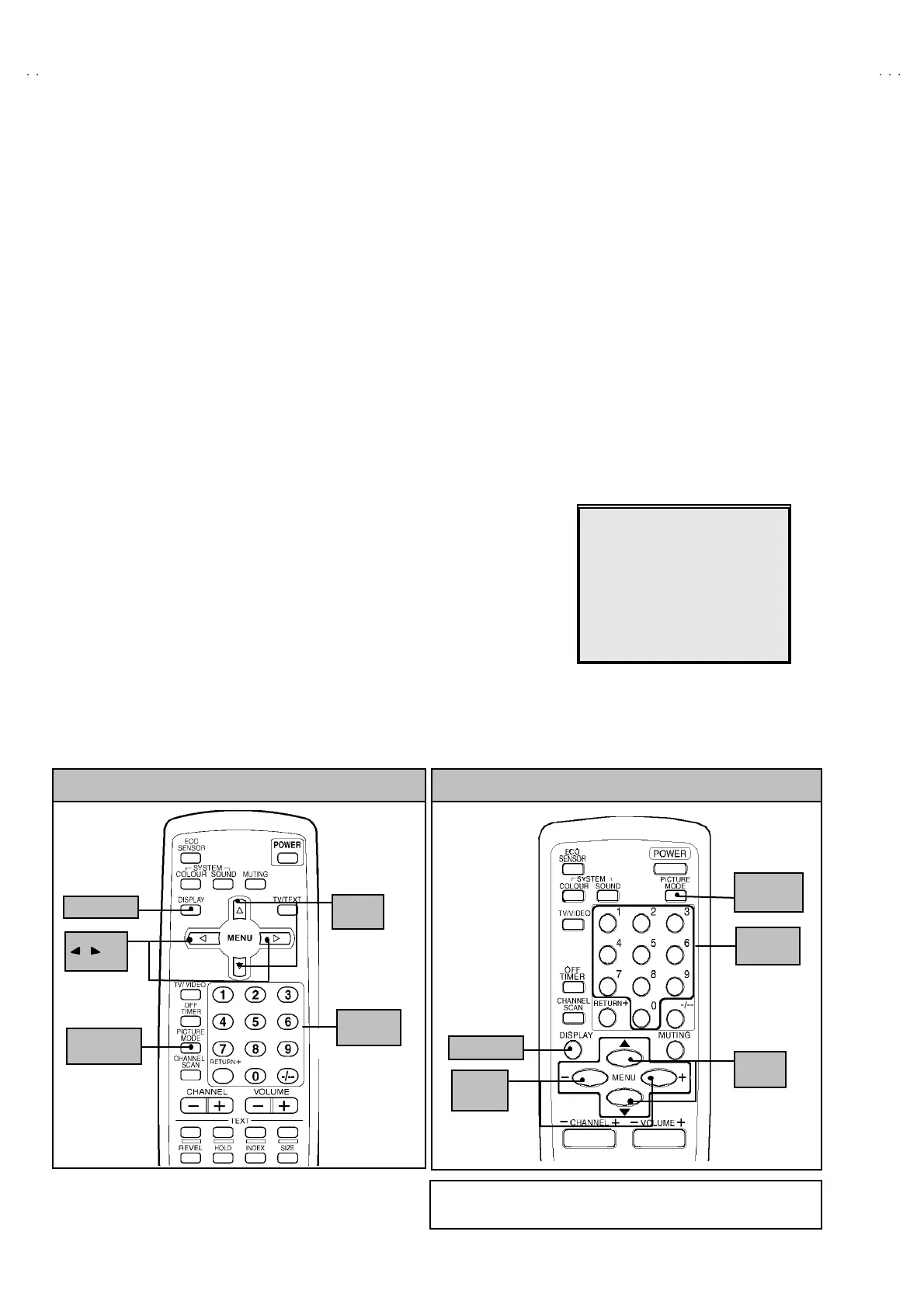
Key operation of the SERVICE MENU
[Enter to SERVICE MENU]
Press the DI SPLAY key and the PICTURE MODE key of the REMOTE CONTROL
UNI T simult an eou sly. Th en ent er the S ERVICE ME NU mod e as sh own in Fig.1 .
[Exit from SERVICE MENU]
When com plete th e ad just ment wor k, pr ess th e DI SPLAY key to return t o th e
SERVICE MENU.
An d then press th e DI SPLAY ke y ag ain, r eturn to th e n or m al screen .
[ Se lec t from SE R VICE M E NU ]
In SERVI CE M ENU, pr ess t he n umber (1 ~6) ke y of th e rem o te c ont ro l un it , to se lect
an y of th e ad justmen t ite ms.
The colo urs which se lected ite m ch aract ers a re ch ang ed .
SE RVICE MENU
1.IF 2.V/C
.DEF 4.V
M PRE
ET
5.PRESET
6.SETUP TOUR OFF
1-6 SELECT DISP : EXIT
******
************
***********
**********
***** **
****
**
.
***
******
***
*** ** **
*** ** ***** ** **
*** ** **** ***
** ***** ***
** ***
Fig.1
(RM-C90)
KEY ASSIGNMENT OF REMOTE CONTROL UNIT
DI SP L A Y k e y
MENU
/ key
MENU
▼
/
▲
key
PICT URE
MO DE ke y
NUMBERS
key
(RM-C364GY)
(RM-C364)
KEY ASSIGNMENT OF REMOTE CONTROL UNIT
MENU
▼/▲ key
MENU
-/+key
DI SP L A Y k e y
PICT URE
MO DE ke y
NUMBERS
key
Exce pt for difference in b ody colo ur , the Remot e Control Uni
RM-C36 4G Y an d RM-C3 64 ha ve e xactly t he same Fu nctio ns.