1-26 (No.YA243)
4.8.5 MTS CIRCUIT
SUB
CONTRAST
Remote
control unit
[1.V/C (S)]
S02: PICTURE
(1) Receive any broadcast.
(2) Select the 1.V/C (S) from the SERVICE MODE.
(3) Select < S02 > (PICTURE).
(4) Set the initial setting value of < S02 >.
(5) If the contrast is not the best with the initial setting
value, make fine adjustment of the < S02 > until you
get the optimum contrast.
Item
Measuring
instrument
Test point Adjustment part Description
Item
Measuring
instrument
Test point Adjustment part Description
MTS INPUT
LEVEL
Remote
control unit
[3.SOUND (A)]
A01: IN LEVEL
(1) Receive any broadcast.
(2) Select the 3.SOUND (A) from the SERVICE MODE.
(3) Select the < A01 > (IN LEVEL).
(4) Set the initial setting value of < A01 >.
MTS
SEPARATION
TV audio
multiplex
signal
generator
Oscilloscope
Remote
control unit
R OUT
L OUT
[AUDIO OUT]
[3.SOUND (A)]
A02: LOW SEP.
A03: HI SEP.
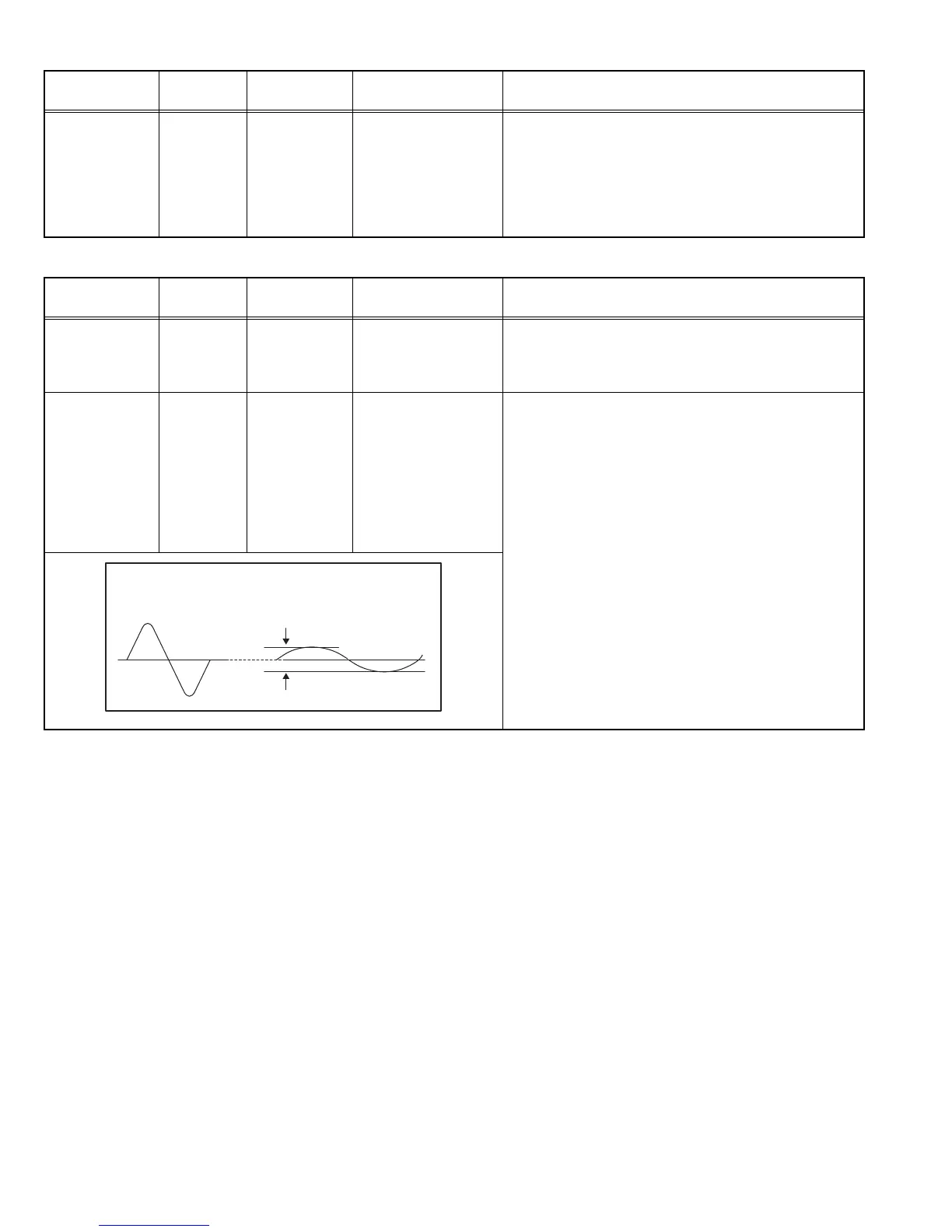
(1) Input the stereo L signal (300 Hz) from the TV audio
multiplex signal generator to the antenna terminal.
(2) Connect an oscilloscope to R OUT pin of the AUDIO
OUT, and display one cycle portion of the 300 Hz
signal.
(3) Select the 3.SOUND (A) from the SERVICE MODE.
(4) Select the < A02 > (LOW SEP.).
(5) Set the initial setting value of < A02 >.
(6) Adjust the < A02 > so that the stroke element of the
300Hz signal will become minimum.
(7) Change the connection of the oscilloscope to L OUT
pin of the AUDIO OUT, and enlarge the voltage axis.
(8) Change the signal to 3 kHz, and similarly adjust
< A03 > (HI SEP.).
L-Channel
signal waveform
R-Channel
crosstalk portion
Minimum
1 cycle
 Loading...