Do you have a question about the JVC AV-27FA44/BSA and is the answer not in the manual?
Explains how to identify models based on naming and features printed on the rating label.
Lists P.W. Board assembly differences for various models, referencing page 3-3.
Parts list for the Main P.W. Board Assembly (SGJ-1524A-M2) of the AV-27FA44/BSA model.
Lists the CRT Socket part number and description for the AV Selector P.W. Board.
Parts list for the Main P.W. Board Assembly (SGJ-1528A-M2) for AV-32FA44/BYA model.
Parts list for the Main P.W. Board Assembly (SGJ-1526A-M2) for AV-32FA44/BZA model.
Indicates the type of equipment covered by the schematic diagrams.
Provides guidelines and explanations for interpreting symbols and notations used in circuit diagrams.
Illustrates the bottom, front, and top views of transistor package types.
Illustrates the bottom, front, and top views of integrated circuit package types.
Shows the block diagram for the AV Selector Printed Wiring Board.
Shows the block diagram for the Main Printed Wiring Board, including tuner and processor functions.
Diagram illustrating the circuit connections for the Front Control Printed Wiring Board.
Diagram showing the circuit for the LED and Power Switch Printed Wiring Board.
Diagram of the circuit connections for the CRT Socket Printed Wiring Board.
Diagram illustrating the circuit for the Digital Audio Filter (DAF) Printed Wiring Board.
First part of the main Printed Wiring Board circuit diagram, detailing component connections.
Lists the Printed Wiring Board Assembly part numbers for various models.
Shows connections from the Main PWB to the AV Selector PWB.
Details the part numbers for the CRT Socket PWB Assembly for various models.
Lists the part numbers for the Front Control PWB Assembly for different models.
Lists the part numbers for the LED & Power SW PWB Assembly for various models.
Lists the part numbers for the DAF PWB Assembly for different models.
Details safety precautions for handling, servicing, and replacing parts to prevent shock, fire, or other hazards.
Highlights key features of the new chassis design and its functionalities.
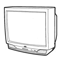
Provides guidance on recognizing and distinguishing between different model series based on labels.
Illustrates the overall system architecture and interconnections of major components.
Details the function of each pin for the Main Microcomputer (MI-COM) or CPU.
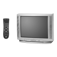
Identifies and describes the function of controls located on the front panel of the TV.
Identifies and describes the function of all terminals and connectors located on the rear panel.
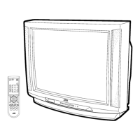
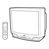
Illustrates the remote control and lists the function of each key.
Provides step-by-step instructions for disassembling the TV set and its various components.
Provides cautions and procedures for degaussing the CRT, emphasizing self-degaussing.
Explains the function and importance of the memory IC in the TV's operation.
Details the step-by-step procedure for replacing the memory IC, including service menu adjustments.
Related to VIDEO / CHROMA circuit adjustment modes.
Related to DEFLECTION circuit adjustment modes.
Related to SOUND circuit adjustment modes.
Whole system related items, fixed values, do not adjust.
3 line YC separation circuit adjustment modes, fixed values, do not adjust.
Used for system setup; fixed values, do not adjust.
Provides cautions regarding handling and replacing chip components to avoid damage.
Recommends the type and wattage of soldering iron for chip component replacement.
Instructions for replacing chip components.
Details prerequisites and methods for performing TV adjustments using remote control or conventional tools.
Lists the necessary measuring instruments and fixtures required for adjustments.
Lists all adjustable parameters within the TV's system.
Shows adjustment locations and wiring for the LED & Power SW PWB.
Shows adjustment locations and wiring for the Front Control PWB.
Shows adjustment locations and wiring for the Main PWB.
Shows adjustment locations and wiring for the AV Selector PWB.
Shows adjustment locations and wiring for the CRT Socket PWB.
Shows adjustment locations and wiring for the DAF PWB.
Explains how to operate the Service Menu using the remote control unit.
Lists the available items within the Service Menu for adjustments and settings.
Guides on basic operations within the Service Menu.
Details setting methods for V/C(S) and DEF(D) items in the Service Menu.
Details setting method for AUDIO(A) items in the Service Menu.
Describes setting method for LOW LIGHT white balance.
Describes setting method for HIGH LIGHT white balance.
Describes setting method for VCO adjustment.
Initial setting values for V/C(S) adjustments (Part 1 of 5) for AV-27FA44 models.
Initial setting values for V/C(S) adjustments (Part 2 of 5) for AV-27FA44 models.
Initial setting values for V/C(S) adjustments (Part 3 of 5) for AV-32FA44 models.
Initial setting values for V/C(S) adjustments (Part 4 of 5) for AV-36FA44 models.
Initial setting values for V/C(S) adjustments (Part 5 of 5) for various models.
Initial setting values for Sound (A) adjustments.
Procedure to check B1 Power Supply, ensuring correct voltage levels.
Adjustment procedures for the tuner and IF circuit.
Procedure for adjusting vertical size and position for 4:3 aspect ratio.
Procedure for adjusting white balance for low light conditions using SCREEN VR.
Adjusts color without instruments by using Service Menu settings.
Adjusts color using an oscilloscope and signal generator for optimal results.
Adjusts tint without instruments by using Service Menu settings.
Adjusts tint using an oscilloscope and signal generator for optimal results.
Procedure to adjust MTS input level to 500mV(rms) using the Service Menu.
Procedure to adjust MTS separation for optimal stereo signal crosstalk.
Details the high voltage hold down circuit and its repair.
Procedure for checking the high voltage hold down circuit operation after repair.
Explains the self-check function and how the ON TIMER LED indicates malfunctions.
Safety cautions for replacing parts, emphasizing the use of specified components.
List of abbreviations used for resistors and capacitors, including their types and tolerances.
Illustrates the exploded view of the TV's external components and their assembly.
Illustrates the exploded view of internal components and their assembly, including PWB parts.
Visual guide showing the assembly of external TV parts and their corresponding part numbers.
Visual guide showing the assembly of internal TV parts and their corresponding part numbers.
Parts list for the Main P.W. Board Assembly (SGJ-1508A-M2) of the AV-27FA44/ASA model.
Parts list for the Main P.W. Board Assembly (SGJ-1510A-M2) for AV-32FA44/AZA model.
Parts list for the Main P.W. Board Assembly (SGJ-1507A-M2) for AV-36FA44/AYA.
Parts list for the Main P.W. Board Assembly (SGJ-1510A-M2) for AV-32FA44/AZA model.
Lists the parts included in the packing for shipment, such as cases and protective materials.
| Display Technology | CRT |
|---|---|
| Screen Size | 27 inches |
| Aspect Ratio | 4:3 |
| Speakers | 2 x 5W |
| Resolution | 480i |
| Inputs/Outputs | RF, Composite, S-Video |