EasyManua.ls Logo

JVC AV-27230/S - User Manual

JVC AV-27230/S
9 pages
Print Icon
To Next Page IconTo Next Page
Loading...
No.51803
Apr. 2001
A
V-27230
1
COPYRIGHT © 2001 VICTOR COMPANY OF JAPAN, LTD.
Apr. 2001
AV-27230
/S
CD-ROM No.SML200104
CONTENTS
!
NOTE ON USING CIRCUIT DIAGRAMS
・・・・・・・・・・・・・・・・・・・・・・・・・・・・・・・・
・・・・・・・・・・・・・・・・・・・・・・・・・・・・・・・・・・・・・・・・・・・・・・・・・・・・・・・・・・・・・・・・
・・・・・・・・・・・・・・・・・・・・・・・・・・・・・・・・ ・・・・・・・・・・・・
・・・・・・・・・・・・・・・・・・・・・・・・
・・・・・・・・・・・・
2-1
!
SEMICONDUCTOR SHAPES
・・・・・・・・・・・・・・・・・・・・・・・・・・・・・・・・
・・・・・・・・・・・・・・・・・・・・・・・・・・・・・・・・・・・・・・・・・・・・・・・・・・・・・・・・・・・・・・・・
・・・・・・・・・・・・・・・・・・・・・・・・・・・・・・・・ ・・・・・・・・・・・・・・・・・・・・・
・・・・・・・・・・・・・・・・・・・・・・・・・・・・・・・・・・・・・・・・・・
・・・・・・・・・・・・・・・・・・・・・
2-2
!
BLOCK DIAGRAM
・・・・・・・・・・・・・・・・・・・・・・・・・・・・・・・・
・・・・・・・・・・・・・・・・・・・・・・・・・・・・・・・・・・・・・・・・・・・・・・・・・・・・・・・・・・・・・・・・
・・・・・・・・・・・・・・・・・・・・・・・・・・・・・・・・ ・・・・・・・・・・・・・・・・・・・・・・・・・・・・・・
・・・・・・・・・・・・・・・・・・・・・・・・・・・・・・・・・・・・・・・・・・・・・・・・・・・・・・・・・・・・
・・・・・・・・・・・・・・・・・・・・・・・・・・・・・・
2-3
!
CIRCUIT DIAGRAMS
・・・・・・・・・・・・・・・・・・・・・・・・・・・・・・・・
・・・・・・・・・・・・・・・・・・・・・・・・・・・・・・・・・・・・・・・・・・・・・・・・・・・・・・・・・・・・・・・・
・・・・・・・・・・・・・・・・・・・・・・・・・・・・・・・・ ・・・・・・・・・・・・・・・・・・・・・・・・・・・・
・・・・・・・・・・・・・・・・・・・・・・・・・・・・・・・・・・・・・・・・・・・・・・・・・・・・・・・・
・・・・・・・・・・・・・・・・・・・・・・・・・・・・
2-5
!
PATTERN DIAGRAMS
・・・・・・・・・・・・・・・・・・・・・・・・・・・・・・・・
・・・・・・・・・・・・・・・・・・・・・・・・・・・・・・・・・・・・・・・・・・・・・・・・・・・・・・・・・・・・・・・・
・・・・・・・・・・・・・・・・・・・・・・・・・・・・・・・・ ・・・・・・・・・・・・・・・・・・・・・・・・・・
・・・・・・・・・・・・・・・・・・・・・・・・・・・・・・・・・・・・・・・・・・・・・・・・・・・・
・・・・・・・・・・・・・・・・・・・・・・・・・・
2-10
!
CHANNEL CHART
・・・・・・・・・・・・・・・・・・・・・・・・・・・・・・・・
・・・・・・・・・・・・・・・・・・・・・・・・・・・・・・・・・・・・・・・・・・・・・・・・・・・・・・・・・・・・・・・・
・・・・・・・・・・・・・・・・・・・・・・・・・・・・・・・・ ・・・・・・・・・・・・・・・・・・・・・・・・・・・・・
・・・・・・・・・・・・・・・・・・・・・・・・・・・・・・・・・・・・・・・・・・・・・・・・・・・・・・・・・・
・・・・・・・・・・・・・・・・・・・・・・・・・・・・・
2-13
BASIC CHASSIS
FD
SCHEMATIC DIAGRAMS
COLOR TELEVISION
Question and Answer IconNeed help?

Do you have a question about the JVC AV-27230/S and is the answer not in the manual?

Summary

Standard Circuit Diagram Usage

Circuit Diagram Safety and Usage Notes

Covers safety critical parts, voltage/waveform conditions, and diagram conventions.

Repair Service Precautions

Important safety guidelines for handling power circuit grounds during repairs.

System Block Diagram

Circuit Diagrams

Main PWB Circuit Diagram

Schematic for the Main Printed Wiring Board.

Main PWB and CRT Socket Circuit Diagram

Schematic for Main PWB and CRT Socket PWB.

Pattern Diagrams

Power PWB Pattern Diagram

Illustrates the physical layout and routing of the power circuit board.

Main and CRT Socket PWB Pattern Diagram

Shows the physical layout and routing for Main and CRT Socket PWBs.

Overview

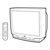
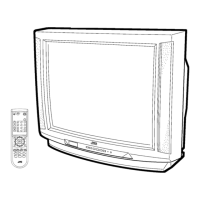
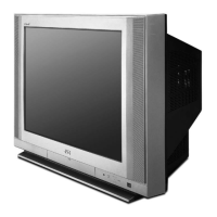
This document provides comprehensive schematic diagrams and technical information for the JVC AV-27230/s Color Television, a model designed for reliable performance and ease of maintenance. The manual is structured to guide technicians through the television's internal workings, from its overall architecture to detailed circuit and pattern layouts.

The JVC AV-27230/s is a color television that integrates various signal processing and control functions to deliver a high-quality viewing experience. Its core functionality revolves around receiving and decoding broadcast signals, processing audio and video, and displaying them on a Cathode Ray Tube (CRT). The television incorporates a sophisticated signal path that handles both analog and digital video inputs, ensuring compatibility with a range of external devices.

Function Description

The television's primary function is to receive and display television broadcasts and external video sources. This is achieved through a series of interconnected modules:

  • Signal Reception and Tuning: The tuner module is responsible for receiving radio frequency (RF) signals from an antenna or cable connection. It selects the desired channel and down-converts the RF signal to an intermediate frequency (IF). The IF amplifier then boosts this signal for further processing.
  • Video Processing: The IF signal, containing both video and audio information, is then routed to the 1CHIP DECODER (IC101). This integrated circuit is a central component, handling various video processing tasks. It separates the luminance (Y) and chrominance (C) components of the video signal, performs demodulation, and converts the analog video into a format suitable for display. The digital comb filter (IC201) plays a crucial role in separating Y and C signals, especially from composite video sources, to reduce artifacts and improve picture clarity. The Y/C SW (IC821) manages the selection and routing of Y/C signals from different inputs.
  • Audio Processing: The audio component of the IF signal is also processed by the 1CHIP DECODER (IC101) and then routed to the MTS&TONE CONTROL (IC651). This module handles multi-channel television sound (MTS) decoding, allowing for stereo or secondary audio program (SAP) reception. It also provides tone control functionalities, enabling users to adjust bass and treble levels. The audio signal then passes through an audio amplifier (IC602) to drive the internal speakers (SP) or external audio outputs. An additional amplifier (IC652) is present for specific audio routing.
  • Input Switching: The television supports multiple audio and video inputs, including composite video, S-Video, and front-panel inputs. The VIDEO SW (IC801) and SW AUDIO (IC631) modules are responsible for selecting the active input source based on user commands. This allows users to connect devices such as VCRs, DVD players, or gaming consoles.
  • Display Control: The processed video signals (R, G, B) are sent to the CRT SOCKET PWB, which drives the CRT (V01). The horizontal (H.DRIVE, Q521) and vertical (V.OUT, IC421) deflection circuits generate the necessary scanning signals to illuminate the CRT screen, forming the image. The Flyback Transformer (FBT, T522) generates high voltage (HV) for the CRT, as well as voltages for heater, X-ray protection, focus, and screen controls.
  • Microcomputer Control: The MICRO COMPUTER (IC701) acts as the brain of the television. It manages all user interactions, including channel selection, volume control, menu navigation, and input switching. It communicates with other ICs and modules, coordinating their operations. The MEMORY (IC702) stores user settings and operational data.
  • Power Supply: The POWER PWB (Power Printed Wiring Board) is responsible for converting the AC mains voltage into the various DC voltages required by the television's internal circuits. It includes a rectifier (D911) and a power regulator (IC921) to ensure stable and regulated power delivery.

Usage Features

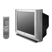
The JVC AV-27230/s is designed for straightforward operation, offering a range of features that enhance the user experience:

  • Remote Control and On-Panel Controls: The television can be operated using a remote control (REMOCON RECEIVER) or through on-panel buttons (KEY). This dual control mechanism provides flexibility for users. An LED indicator provides visual feedback on the television's status.
  • Multiple Input Options: With composite video, S-Video, and front-panel inputs, the television offers versatility for connecting various external devices. This allows users to easily switch between different entertainment sources.
  • Audio Customization: The MTS&TONE CONTROL module enables users to adjust audio settings, including bass and treble, to suit their preferences. This allows for a personalized audio experience.
  • Channel Management: The MICRO COMPUTER facilitates easy channel selection and management. The CHANNEL CHART sections in the manual provide detailed listings of US and CA channels, indicating their corresponding modes (VL, VH, MID, SUPER, HYPER, ULTRA) and tuner bands. This helps users understand the channel lineup and how to access specific channels.
  • User-Friendly Interface: While not explicitly detailed in the functional description, the presence of a microcomputer and memory suggests a menu-driven interface for adjusting settings, which is typical for televisions of this era.

Maintenance Features

The manual is primarily a maintenance guide, providing critical information for servicing the JVC AV-27230/s. Several features are incorporated to aid technicians in troubleshooting and repair:

  • Detailed Schematic Diagrams: The "CIRCUIT DIAGRAMS" section provides comprehensive schematics for the MAIN PWB, CRT SOCKET PWB, and POWER PWB. These diagrams illustrate the interconnections of components, allowing technicians to trace signal paths and identify faulty sections. Components critical for safety are identified by a symbol and shading, emphasizing the importance of using manufacturer-recommended parts for replacement.
  • Pattern Diagrams: The "PATTERN DIAGRAMS" section shows the physical layout of components on the POWER PWB and MAIN PWB/CRT SOCKET PWB. These diagrams are essential for locating specific components on the circuit boards during repair.
  • Standard Circuit Diagram Notes: The "STANDARD CIRCUIT DIAGRAM" section provides crucial notes on using the circuit diagrams. This includes:
    • Safety Information: Highlights components critical for safety and stresses the importance of using original manufacturer parts for replacement to ensure continued safety.
    • Specified Voltage and Waveform Values: Details the conditions under which voltage and waveform values were measured (e.g., input signal, setting positions, tester resistance, oscilloscope sweeping time). This allows technicians to compare measured values with expected values for diagnostic purposes. Test points are clearly indicated.
    • Indication of Parts Symbol: Explains the symbols and notations used for resistors, capacitors, coils, and power supply components, including their values, types, and ratings. This ensures accurate identification of components.
    • Ground Symbol Explanation: Clarifies the different ground symbols used (LIVE side ground, ISOLATED (NEUTRAL) side ground, EARTH ground, DIGITAL ground). This is particularly important for safety and proper measurement.
    • Note for Repairing Service: Provides critical safety warnings regarding the television's power circuit, which has different GNDs (LIVE and ISOLATED/NEUTRAL). It explicitly warns against touching both GNDs simultaneously or shorting them, as this can cause electric shock or damage to the unit. It also advises removing the power cord before servicing.
  • Semiconductor Shapes: The "SEMICONDUCTOR SHAPES" section provides diagrams of transistor, IC, and chip IC packages, aiding in the correct identification and orientation of these components.
  • Block Diagram: The "BLOCK DIAGRAM" provides a high-level overview of the television's architecture, showing the main functional blocks and their interconnections. This helps technicians understand the overall signal flow and pinpoint the general area of a problem before delving into detailed schematics.
  • CD-ROM Reference: The manual indicates that it is a CD-ROM (No.SML200104), suggesting that additional digital resources or updated information might be available, which is a modern approach to documentation.
  • Copyright and Revision Information: The copyright notice and revision date (Apr. 2001) provide context for the document's currency and intellectual property. The note about circuit diagrams being standard and subject to change without notice for improvement is a common disclaimer, reminding technicians that minor variations might exist in production units.

In summary, the JVC AV-27230/s is a color television designed with a focus on comprehensive functionality and maintainability. The provided manual serves as an indispensable resource for technicians, offering detailed insights into its operation, component layouts, and crucial safety guidelines for effective servicing.

JVC AV-27230/S Specifications

General IconGeneral
Screen Size27 inches
Display TechnologyCRT
Aspect Ratio4:3
Comb Filter3-Line Digital
Resolution480i
InputsComposite, S-Video

Related product manuals