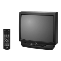
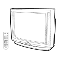
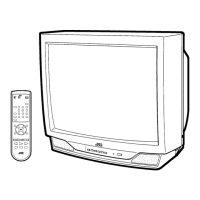
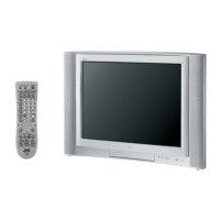
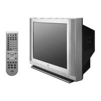
This document serves as a comprehensive service manual for the JVC AV-27530/sc Color Television, identified by the basic chassis FE5. It provides detailed information for servicing, maintenance, and understanding the operational aspects of the television.
Function Description
The JVC AV-27530/sc is a color television designed for home entertainment. It supports various video and audio input sources, including broadcast television channels and external devices. Key features include:
- Video Status: Allows users to select a favorite screen from the VIDEO STATUS menu.
- Component Input: Equipped with a component signal input terminal, ensuring direct video reproduction without deterioration from DVD sources.
- V-CHIP: Built-in V-CHIP functionality enables users to choose, view, and listen to healthy programming.
- MTS Stereo: Incorporates the MTS system (Multi-channel Television Sound system) for voice multiplex function.
- Return Plus: Provides a specific channel return function, allowing users to navigate through channels using the CH+ and CH- keys.
Important Technical Specifications
The television boasts a range of technical specifications that define its performance and capabilities:
Dimensions and Weight:
- Dimensions (W × H × D): 65.4 cm × 59.3 cm × 49.4 cm (25-3/4" × 23-3/8" × 19-1/2")
- Mass: 31.1 kg (68.5 lbs)
Display:
- TV RF System: CCIR (M)
- Color System: NTSC
- Sound System: BTSC (Multi Channel Sound)
- Picture Tube (Visible size): 68 cm (27") Measured diagonally (H: 55.4 cm × V: 41.8 cm)
- High Voltage: 30.0 kV ±1.2 kV [at Zero beam current]
Audio:
- Speaker: 5 cm × 9 cm (2" × 3-1/2"), Oval type × 2
- Audio Power Output: 1.2 W + 1.2 W
Tuner and Channels:
- Television System: Closed Caption (T1 - T4 / CC1 - CC4)
- TV Receiving Channels and Frequency:
- VHF low: 06ch - 06ch; 48 MHz - 88 MHz
- VHF high: 07ch - 13ch; 174 MHz - 216 MHz
- UHF: 14ch - 69ch; 470 MHz - 806 MHz
- CATV (MMDS): 90ch; 904 MHz
- Low Band: 01 - 06
- High Band: 07 - 13
- Mid Band: 14 - 22
- Super Band: 23 - 36
- Hyper Band: 37 - 64
- Ultra Band: 65 - 94, 100 - 135
- Sub Mid Band: 01, 96 - 99
- TV / CATV Total Channel: 181 Channels (Reception of channel A-5 ("95" of the TV set's on-screen CABLE channel) is recommended for your TV set.)
Inputs/Outputs:
- Intermediate Frequency: Video IF 45.75 MHz, Sound IF 41.25 MHz (4.5 MHz)
- Color Sub Carrier: 3.58 MHz
- Antenna Terminal (VHF / UHF): F-type connector, 75 Ω unbalanced
- Video / Audio Input [Input-1/2/3]:
- Component Video: RCA pin jack × 3
- [Input-2]: Y: 1V(p-p), 75 Ω, negative sync
- PB/PR: 0.7 V(p-p), 75 Ω
- S-video: Mini DIN 4-pin connector × 1
- [Input-1]: Y: 1V(p-p), 75 Ω, negative sync
- C: 0.286 V(p-p)(burst signal), 75 Ω
- Video: 1 V(p-p), 75 Ω, negative sync, RCA pin jack × 2
- Audio: 500 mV(rms)(-4dBs), high impedance, RCA pin jack × 6
- Audio Output (Fix): 500 mV(rms)(-4dBs), low impedance, (400 kHz when modulated 100 %), RCA pin jack × 2
Power:
- Power Input: AC120 V, 60 Hz
- Power Consumption: 105 W
Remote Control:
- Remote Control Unit: RM-C203 (Lithium cell battery × 1)
Usage Features
The manual outlines several user-centric features and operational guidelines:
Service Menu Operation:
The television features a service menu accessible via the remote control unit, allowing for detailed adjustments.
- Accessing the Service Menu: To enter the service mode, set to 0 minutes using the [SLEEP TIMER] key. Press the [VIDEO STATUS] key and [DISPLAY] key simultaneously while "0 MIN" is displayed to enter the service mode.
- Saving Settings: The setting value will be stored automatically when releasing the REMOTE CONTROL UNIT keys.
- Exiting Service Mode: Press the [EXIT] key to exit the SERVICE MODE.
Menu Items and Adjustments:
The service menu includes various items for fine-tuning the television's performance:
- 1. V/C (S): Adjusts video settings (S01-S21).
- 2. DEF (D): Adjusts deflection settings (D01-D12).
- 3. SOUND (A): Adjusts audio settings (A01-A09).
- 4. OTHERS (F): Adjusts factory settings (F01-F09).
- 7. LOW LIGHT: Adjusts white balance (low light) control circuit.
- 8. HIGH LIGHT: Adjusts white balance (high light) control circuit.
- 9. VCO: Adjusts VCO control circuit.
- 11. I2C BUS: Adjusts I2C BUS settings.
Remote Control Menu Operation:
The manual also details typical remote control operations for picture, sound, clock/timers, and initial setup adjustments.
- Picture Adjust: TINT, COLOR, PICTURE, BRIGHT, DETAIL, NOISE MUTING.
- Sound Adjust: BASS, TREBLE, BALANCE, MTS.
- Clock / Timers: SET CLOCK, ON / OFF TIMER.
- Initial Setup: INPUT, CHANNEL, VOLUME, MUTING, DISPLAY, SLEEP TIMER, VIDEO STATUS.
Maintenance Features
The service manual provides extensive information for proper maintenance and repair, emphasizing safety and correct procedures.
Safety Precautions (Section 1):
- General Safety: Highlights the importance of using specified parts, adhering to design specifications, and ensuring proper training for service personnel.
- Electrical Safety: Emphasizes checking for electrical shock hazards, ensuring proper grounding, and performing leakage current tests.
- Hot Chassis: Warns about the "hot chassis" design and the need for an isolation transformer during service.
- High Voltage: Instructs to discharge the high voltage before working on the CRT anode and to use a high voltage probe with a VTVM for measurement.
Disassembly Procedures (Section 3):
- Removing the Rear Cover: Disconnect power, remove screws, and withdraw the rear cover.
- Removing the Main PWB: Remove the rear cover, raise the main PWB, and remove the PWB stopper from the cabinet.
- Removing the Speaker: Remove screws and the speaker.
- Checking the Main PWB: Instructions for checking the PWB from the back side, pulling out the main PWB, and verifying its vertical side.
- Wire Clamping and Cable Tying: Ensures proper clamping and tying of wires.
Memory IC Replacement (Section 3.2):
- Procedure: Details steps for power off, replacing the memory IC, and power on.
- Receiving Channel Setting: Refers to the OPERATING INSTRUCTIONS (USER'S GUIDE) for setting channels.
- User Settings: Refers to the "SETTINGS OF FACTORY SHIPMENT" table for checking user settings.
- Service Mode Setting: Verifies settings in the SERVICE MODE.
Replacement of Chip Component (Section 3.3):
- Cautions: Provides guidelines for heating time, electrode and resist parts, removing, and reusing chip parts.
- Soldering Iron: Recommends using a high insulation soldering iron with a thin pointed end and a 30W soldering iron for easy removal.
- Replacement Steps: Detailed instructions for removing and installing chip parts (resistors, capacitors, transistors, diodes, variable resistors).
Adjustment Preparation (Section 4):
- Adjustment Methods: Explains two ways to adjust the TV: using the REMOTE CONTROL UNIT and using adjustment parts and components.
- Initial Setting Values: Emphasizes using the REMOTE CONTROL UNIT to adjust settings to the optimum condition.
- Power Supply: Ensures correct AC to AC power source.
- Warm-up: Advises warming up the TV for at least 30 minutes before starting adjustments.
- Signal Input: Specifies using the most appropriate signal for adjustment.
- Parts Handling: Warns against touching variable resistors, transformers, and condensers not shown in the adjustment items.
Preset Setting Before Adjustments (Section 4.2):
- Video Status: STANDARD
- Picture Adjustment: ALL.00
- Sound Adjustment: ALL.00
Measuring Instrument and Fixtures (Section 4.3):
- Lists necessary tools: DC voltmeter, oscilloscope, signal generator (Pattern generator) [NTSC], TV audio multiplex signal generator, and remote control unit.
Adjustment Items (Section 4.4):
- Check Item: DC VOLTAGE check, HIGH VOLTAGE HOLD DOWN check.
- Focus: FOCUS adjustment.
- Deflection Circuit: V. SIZE / V. POSITION adjustment, H. POSITION / H. SIZE / SIDE PIN adjustment.
- Video Circuit: WHITE BALANCE (High Light & Low Light) adjustment, SUB BRIGHT adjustment, SUB CONTRAST adjustment.
- MTS Circuit: MTS INPUT LEVEL adjustment, MTS SEPARATION adjustment.
Adjustment Procedure (Section 4.8):
- Check Item (B1 POWER SUPPLY, HIGH VOLTAGE HOLD DOWN): Detailed steps for measuring and adjusting.
- Tuner / IF Circuit (IF VCO): Instructions for adjusting the VCO.
- Focus (FOCUS): Steps for adjusting the focus.
- Deflection Circuit (V. SIZE / V. POSITION, H. SIZE / H. POSITION / SIDE PIN): Detailed adjustment procedures for screen size and position.
- Video Circuit (WHITE BALANCE (LOW LIGHT), WHITE BALANCE (HIGH LIGHT), SUB BRIGHT, SUB CONTRAST): Comprehensive steps for video adjustments.
- MTS Circuit (MTS INPUT LEVEL, MTS SEPARATION): Procedures for adjusting MTS settings.
Parts List (Section 3 of Parts List):
- Provides a comprehensive list of all components, including resistors, capacitors, transistors, diodes, and integrated circuits, with their part names, descriptions, and local identifiers. This is crucial for identifying and ordering replacement parts.
Exploded View (Section 3 of Parts List):
- Offers a visual representation of the television's components and their assembly, aiding in disassembly and reassembly processes.
Schematic Diagrams (Section 2 of Schematic Diagrams):
- Includes detailed block diagrams and circuit diagrams for the main PWB and CRT socket PWB, showing interconnections and component layouts, essential for troubleshooting and repair.
Pattern Diagrams (Section 2 of Schematic Diagrams):
- Provides main PWB and CRT socket PWB patterns, indicating component placement and trace routing, which are vital for identifying components and tracing signals during repair.
This manual ensures that service personnel have all the necessary information to safely and effectively maintain and repair the JVC AV-27530/sc Color Television, extending its lifespan and ensuring optimal performance.