Do you have a question about the JVC CD-1770 and is the answer not in the manual?
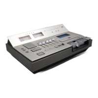
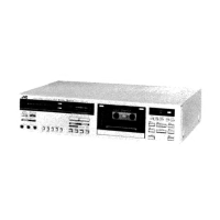
Displays unit status, signal levels, and noise reduction activity.
Buttons and switches for playback, recording, and noise reduction.
Ports for connecting microphones, headphones, and line audio.
Controls related to tape loading and status indication.
Procedure to remove the top protective cover for heads.
Procedure to remove the cassette loading door.
Procedure to remove the volume control knobs.
Procedure to remove the bottom panel of the unit.
Procedure to remove the power switch knob.
Procedure to remove the eject mechanism knob.
Procedure to remove EQ and Bias switch knobs.
Procedure to remove the front panel assembly.
Procedure to remove the main amplifier board.
Procedure to remove the ANRS circuit board.
Procedure to remove the switch circuit board.
Procedure to remove the power transformer.
Procedure to remove the microphone jack assembly.
Procedure to remove volume and level controls.
Procedure to remove the power switch component.
Procedure to remove the main mechanical assembly.
Procedure to remove the drive motor.
Procedure to remove the flywheel.
Procedure to remove the pinch roller assembly.
Procedure to remove the take-up reel disc.
Procedure to remove the supply reel disc.
Adjusting the VU meter sensitivity and zero point.
Adjusting the peak indicator thresholds.
Adjusting playback output level.
Adjusting bias current for optimal recording.
Adjusting recording signal level.
Adjusting parameters for the ANRS noise reduction system.
Adjusting head alignment for record/playback.
Adjusting the height of the erase head.
Adjusting the motor rotational speed.
Adjusting tape take-up tension.
Adjusting fast forward tape tension.
Adjusting rewind tape tension.
Adjusting the auto-stop mechanism.
Adjusting the timer recording mechanism.
Adjusting the door brake mechanism.
Troubleshooting electrical problems affecting sound quality.
Troubleshooting mechanical problems like wow and flutter.
Procedures for cleaning heads, capstan, and pinch roller.
Process for demagnetizing tape heads.
Diagram illustrating the signal path during recording.
Diagram illustrating the signal path during playback.
Lists components for the main amplifier board.
Diagram and components for the bias switch board.
Diagram and components for the equalizer switch board.
Diagram and components for the peak level indicator board.
| Total Harmonic Distortion | 1.0% |
|---|---|
| Brand | JVC |
| Model | CD-1770 |
| Motor | DC motor |
| Tape Type | Normal, CrO2, Metal |
| Frequency Response | 30Hz to 16kHz (Metal Tape) |
| Playback Functions | Stop |
| Power Source | AC 220V, 50Hz |