Do you have a question about the JVC CD-1920 and is the answer not in the manual?
Details type, tracks, cassette compatibility, frequency response, S/N, wow/flutter, crosstalk, distortion, bias, erasure, and heads.
Covers motor, tape speed, timings, power requirements, consumption, dimensions, and weight.
Lists specifications for input jacks, output jacks, and DIN connector.
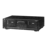
Lists distinct capabilities like "Vertical-open-view" deck, ANRS, auto stop, and air-damped door.
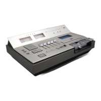
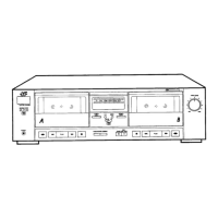
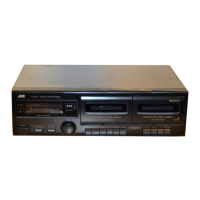
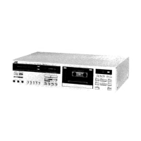
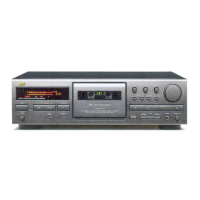
Identifies and explains controls and indicators on the front panel (1-15).
Identifies and explains rear panel connections and controls (16-29).
Labels and lists the primary internal components within the unit.
Explains the function and circuit design of the multi-point peak level indicators.
Steps for removing outer panels and the cassette door.
Procedures for removing internal electrical and mechanical assemblies.
Instructions for removing the cassette holder and the main mechanism assembly.
Steps for detaching the motor, flywheel, and related components.
Procedures for removing pinch roller, take-up disc, supply disc, and flywheel holder.
Details calibration steps for level meters, peak level, playback sensitivity, bias, recording signal, and ANRS.
Covers adjustments related to head azimuth and motor speed.
Lists common electrical issues like poor tone quality and recording problems with potential causes.
Identifies mechanical issues related to wow/flutter, capstan, pinch roller, belts, and back tension.
Provides repair actions for common mechanical failures like take-up torque and door issues.
Instructions for cleaning heads, pinch roller, capstan, and the cabinet.
Steps for demagnetizing the heads using a demagnetizer.
Illustrates power connection schematics for different model variations (CD-1920A/B, CD-1920E, CD-1920U).
Detailed schematic of the main circuit board and interconnected components.
Illustrates connections for ANRS, Power Supply, Cds, MIC Jack, Indicator, and Head Terminal boards.
Presents a comprehensive schematic of the entire audio system including input, processing, and output stages.
Shows power supply diagrams for CD-1920C, CD-1920A/B, and CD-1920E models.
Illustrates the signal flow and component interaction during the recording process.
Shows the signal path and functional blocks for audio playback.
Lists reference numbers, part numbers, and quantities for components on the main amplifier board.
Lists various capacitors, resistors, V. resistors, and transistors with their specifications.
Includes inductors, diodes, switches, and integrated circuits for circuit boards.
Shows the physical layout of components on the ANRS circuit board.
Details resistors, capacitors, and V. resistors used on the ANRS circuit board.
Lists diodes, integrated circuits, and inductors for the ANRS circuit board.
Illustrates the component placement on the power supply circuit board.
Details resistors and capacitors for the power supply circuit board.
Lists transistors, SCRs, diodes, heat sinks, fuse holders, and fuses for the power supply board.
Shows the layout of the peak level circuit board and indicates adjustment points.
Lists resistors, capacitors, diodes, transistors, and ICs for the peak level circuit board.
Lists components for the MIC Jack and Indicator circuit boards, including resistors, capacitors, LEDs, and tabs.
Details components for the Head Terminal and Cds circuit boards, including resistors and LEDs.
Lists parts related to the chassis, brake arm, brake lever, and related components.
Details parts for the capstan, R.P. head, E. head, and pinch roller mechanisms.
Lists parts for tape transport, such as take-up disk, supply disk, motor, and various levers and springs.
Illustrates the arrangement of various mechanical components on the chassis.
Shows the placement of levers, brackets, and switches within the mechanism.
Depicts the arrangement of drive mechanism parts like flywheels, pulleys, and belts.
Shows the placement of actuators, levers, and bracket components.
Lists parts related to the cassette holder, solenoid, and related brackets and springs.
Details various levers, springs, nuts, and screws used in the mechanical assemblies.
Lists parts for enclosure, buttons, shafts, brackets, pilot lamps, and rubber cushions.
Details power cords, connectors, meter escutcheons, level meters, shafts, and front panel parts.
Provides an exploded view showing the assembly of enclosure and external electrical parts.
Details the contents of the packing case and lists included accessories like cords, sticks, and manuals.
| Brand | JVC |
|---|---|
| Model | CD-1920 |
| Category | Cassette Player |
| Language | English |