1-14 (No.PA048<Rev.002>)
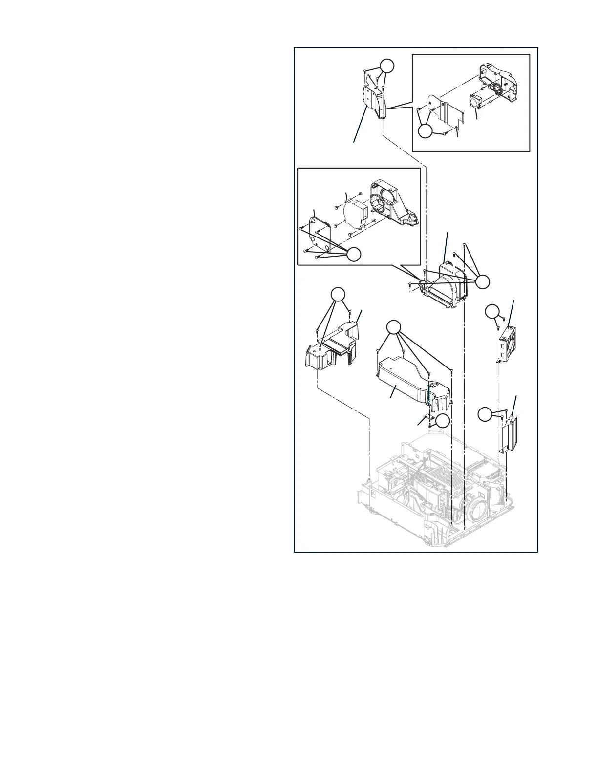
3.2.13 REMOVING THE BLIND INTAKE (Fig.3-3)
(1) Remove the 2 screws [A], then remove the BLIND IN-
TAKE.
3.2.14 REMOVING THE INTAKE FAN (Fig.3-3)
(1) Remove the 2 screws [B], then remove the INTAKE FAN.
3.2.15 REMOVING THE PCS COOLING FAN [X700R, 900R,
XC7880R] (Fig.3-3)
(1) Remove the 3 screws [C], then remove the FAN UNIT-1.
(2) Remove the 3 screws [D], then remove the IRIS DUCT
COVER.
(3) Remove the PCS COOLING FAN.
3.2.16 REMOVING THE DEVICE COOLING FAN (Fig.3-3)
(1) Remove the 4 screws [E], then remove the FAN UNIT-2.
(2) Remove the 4 screws [F], then remove the OE COVER.
(3) Remove the DEVICE COOLING FAN.
3.2.17 REMOVING THE EXHAUST DUCT COVER (Fig.3-3)
(1) Remove the 3 screws [G], then remove the EXHAUST
DUCT COVER.
3.2.18 REMOVING THE TOP DUCT (Fig.3-3)
(1) Remove the 4 screws [H], then remove the TOP DUCT.
3.2.19 REMOVING THE TEMP SENSOR PWB (Fig.3-3)
(1) Remove the 1 screw [J], then remove the TEMP SENSOR
PWB.
Fig.3-3
[X700R, 900R, XC7880R]
AA
JJ
BB
CC
DD
HH
GG
EE
FF
EXHAUST DUCT COVER
TOP DUCT
FAN UNIT-1
FAN UNIT-2
BLIND INTAKE
TEMP SENSOR PWB
IRIS DUCT COVER
PCS COOLING FAN
OE COVER
DEVICE COOLING FAN
INTAKE FAN
 Loading...