(No.PA048<Rev.002>)1-15
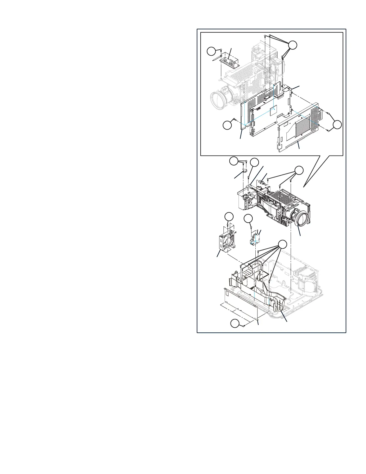
3.2.20 REMOVING THE LAMP COOLING FAN (Fig.3-4)
(1) Remove the 2 hooks [A], then remove the LAMP COOL-
ING FAN.
3.2.21 REMOVING THE EXHAUST DUCT FAN (Fig.3-4)
(1) Remove the 4 hooks [B], then remove the EXHAUST
DUCT FAN.
3.2.22 REMOVING THE OPTICAL BLOCK (Fig.3-4)
(1) Remove the 3 screws [C], then remove the TEMP SEN-
SOR.
(2) Remove the 3 screws [D], then remove the CONNECTOR
BRACKET and CONNECTOR.
(3) Remove the 3 screws [E], then remove the OPTICAL
BLOCK.
3.2.23 REMOVING THE MOTOR PWB (Fig.3-4)
(1) Remove the 4 screws [F], then remove the MOTOR PWB.
3.2.24 REMOVING THE DD PWB (Fig.3-4)
(1) Remove the 4 screws [G], then remove the DD SHIELD
CASE.
(2) Remove the 2 screws [H], then remove the DD SHIELD
TOP.
(3) Remove the 4 screws [J], then remove the DD PWB.
3.2.25 REMOVING THE BOTTOM DUCT (Fig.3-4)
(1) Remove the 5 screws [K], then remove the BOTTOM
DUCT.
3.2.26 REMOVING THE SHIELD LEFT (Fig.3-4)
(1) Remove the 3 screws [L], then remove the SHIELD LEFT.
Fig.3-4
EXHAUST DUCT FAN
LAMP COOLING FAN
MOTOR PWB
DD SHIELD TOP
DD SHIELD BOTTOM
TEMP SENSOR
CONNECTOR BRACKET
CONNECTOR
DD PWB
BOTTOM DUCT
OPTICAL BLOCK
SHIELD LEFT
AA
JJ
CC
FF
LL
BB
DD
EE
GG
KK
HH
 Loading...