Do you have a question about the JVC DLA-X500RBE and is the answer not in the manual?
General specifications for the D-ILA projector.
Optical specifications including projection system and lens.
Electrical specifications including video input and 3D signal formats.
Details of the projector's input, output, and control connectors.
Guidelines for safe servicing procedures and handling of parts.
Further safety advice and precautions for handling the projector.
Step-by-step instructions for physically installing the projector.
Advice on selecting an appropriate installation environment and spacing.
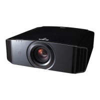
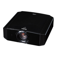
Highlights differences between various projector models.
Lists part numbers and repair methods for PCBs and blocks.
Describes the meaning of various LED status lights on the projector.
Identifies the location and function of the projector's operation buttons.
Illustrates the placement of input and output terminals on the projector.
Information on lamp lifespan, replacement, and handling cautions.
Procedure to reset the lamp usage timer after replacement.
Details on projection distance and resulting image size.
Steps to enter and navigate the service menu.
Lists and describes configurable options available in the service menu.
Warnings and essential precautions before starting disassembly.
Steps to remove lamp unit, side panel, top cabinet, front panel.
Procedures for removing LED&IR PWB, lens cover, etc.
Steps to remove rear panel, keypad PWB, terminal PWBs.
Procedures for removing intake fans, cooling fans, and duct covers.
Steps to remove lamp cooling fan, optical block, motor PWB.
Procedures for removing DD PWB, bottom duct, and shield left.
Steps to remove processor PWB, DD cooling fan, DD sub PWB.
Procedures for removing ballast PWB, exhaust fan, and center/power shields.
Steps to remove power PWB, AC connector, lamp cover PWB.
Procedure for removing the main bottom chassis.
Steps before adjustment and list of necessary instruments.
Required adjustments after replacing internal components.
Procedure to back up the main EEPROM data.
Instructions for writing the correct model code.
Procedure to write the destination settings.
Steps to transfer CMS data from DD SUB PWB.
Procedure to back up data from the DD SUB PWB.
Adjusting pixel shift and resetting lens position.
Procedure to write the MAC address.
Explains protective sensors and their functions.
Details on LED indicators for troubleshooting errors.
How to load and view error log data from the projector.
Configuration of fan speed based on temperature.
Steps to update the projector's main CPU firmware.
Instructions for updating the boot loader software.
Procedure to write HEX files using Flash Magic software.
Steps to update the DD CPU firmware.
Illustrates the interconnection of various PCBs in the projector.
Shows the functional flow between different processing units.
Details the functions of the Main CPU and Input FPGA.
Explains the functions of VP FPGA and PA168 (MEMC).
Outlines the functions of DD FPGA and DD CPU.
| Resolution | 1920 x 1080 |
|---|---|
| Brightness | 1300 ANSI Lumens |
| Throw Ratio | 1.4:1 - 2.8:1 |
| 3D | Yes |
| Lamp Life | 4000 hours |
| Projection Technology | DLP |
| Lens Shift | Vertical: +/- 80%, Horizontal: +/- 34% |
| Inputs | HDMI x 2, Component x 1, Composite x 1, RS-232C |
| Projection Size | 60 - 200 inches |