1-22 (No.MB487)
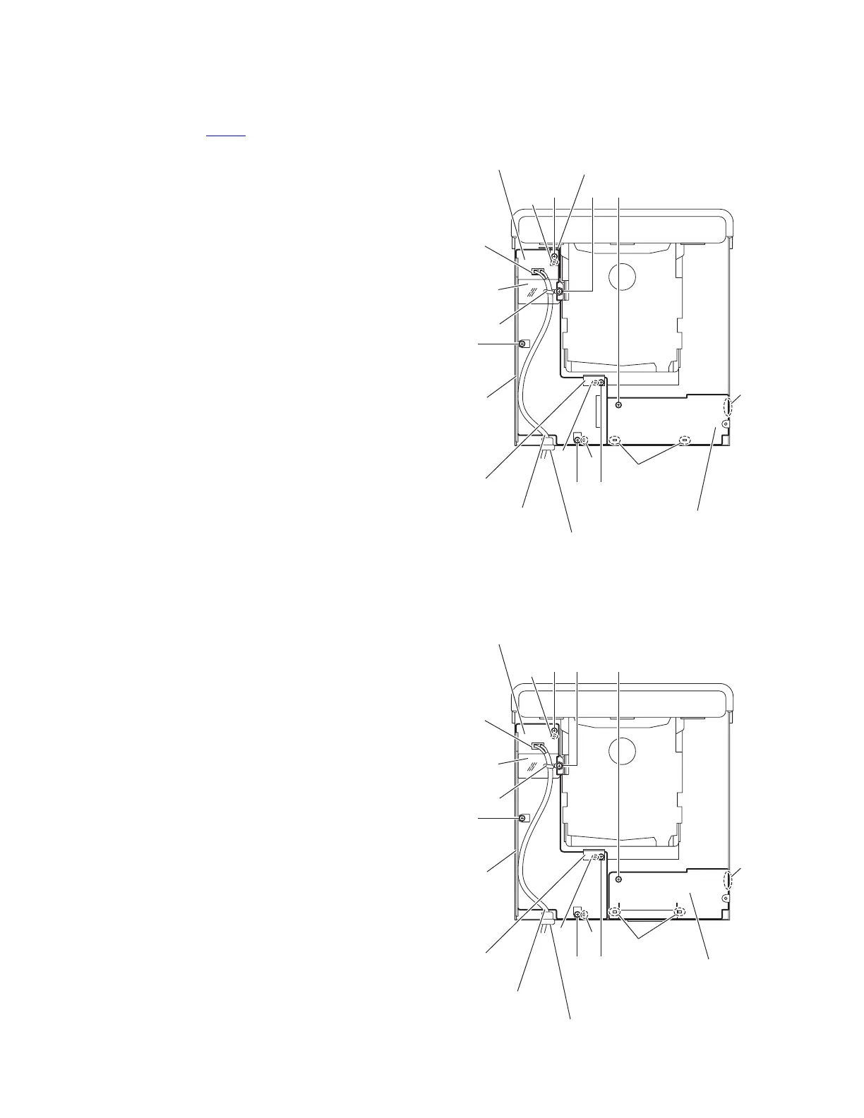
3.2.5 Removing the power supply board
(See Fig.10)
• Remove the metal cover, rear panel and main board.
(1) From the top side of the main body, disconnect the power
cord from the connector CN201 on the power supply board.
(2) Remove the strain relief attaching the power cord to the
bottom chassis in an upward direction and remove the
power cord.
Reference:
Remove the tie band as required.
(3) Remove the two screws H, screw J and screw J' attaching
the power supply board.
Reference:
• When attaching the screw J, attach the FFC barrier
with it.
• When attaching the screw J', attach the PRI. barrier
with it. [For U.S.A./Canada]
(4) Remove the screw K attaching the wire holder.
Reference:
When attaching the screw K, attach the barrier with it.
[Excep for U.S.A./Canada]
(5) Take out the power supply board.
Reference:
When attaching the power supply board, attach it after fitting
the projections (e, f) of the main body in the holes of the power
supply board.
3.2.6 Removing the video jack board
(See Fig.10)
• Remove the metal cover, rear panel and main board.
• Remove the power supply board. [For U.S.A/Canada/Asia/
South America/U.S. Military/Middle East/South Africa]
Reference:
Remove the earth wires as required.
(1) Remove the screw M attaching the video jack board.
(2) Take out the video jack board from the main body.
Reference:
• When attaching the video jack board, attach it after fitting the
projections g of the main body in the holes of the video jack
board.
• When attaching the video jack board, attach it after fitting the
section h of the video jack board in the holes of the bottom
chassis. [For U.S.A/Canada/Asia/South America/U.S.
Military/Middle East/South Africa]
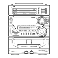
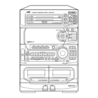
Fig.10
CN201
Power supply board
Wire
holder
FFC barrier
Video jack board
Strain relief
Power cord
Bottom
chassis
f
f
g
e
J'
H
M
JH
K
CN201
Power supply board
Wire
holder
FFC barrier
Strain relief
Power cord
Bottom
chassis
f
f
g
e
J'
H
M
JH
K
Barrier
[For Europe]
[For U.S.A/Canada/Asia/South America
/U.S. Military/Middle East/South America]
h
Barrier
Video jack board
h
PRI. barrier
 Loading...