1-18 (No.YF219)
SECTION 5
TROUBLE SHOOTING
5.1 SERVICE NOTE
[11]
3-2-18
[1] [2] [4][3] [5] [6] [9] [10] [11][7] [8]
- 1 2 3 4 5 6 7 8 9 10 - 11 12 13 14 15 16 17 18 19 20 21 22 23 24 25
3-2-2-1
3-2-1
3-2-8
3-2-12 3-2-17
3-2-3-1 3-2-4-1 3-2-4-3
aa
3-2-5 3-2-6 3-2-7
ac
[12] [13] [14] [15] [16] [17] [18] [19] [20] [21]
26 27 28 29 30 31 32 33 34 35 36 37 38 39 40 41 42 43 44 45 46 47 48 49 50 51
3-2-9 3-2-10 3-2-11 3-2-13 3-2-14
a ab
3-2-15 3-2-16
1 2 3 4 5 6 7 8 9
-
--
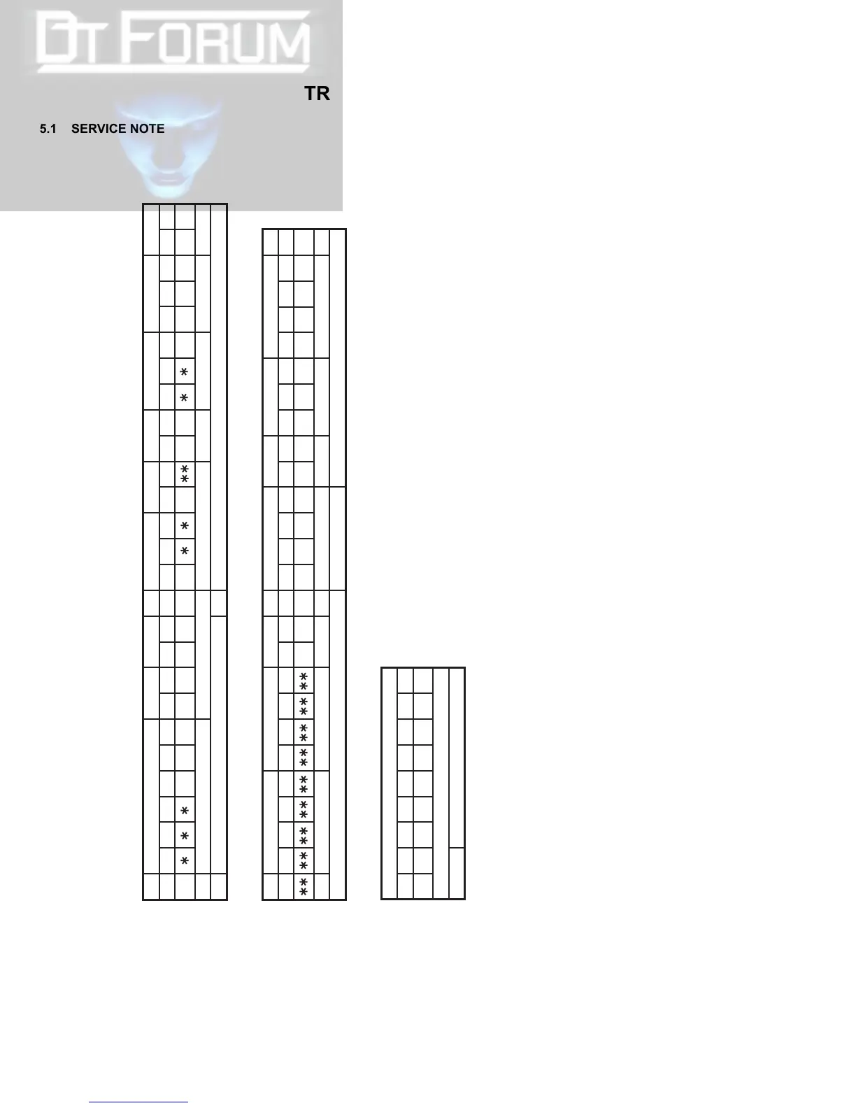
Symbol No.
Removing order of screw
Place to stick screw
Reference drawing (Fig.No.)
Screw tightening torque
Symbol No.
Removing order of screw
Place to stick screw
Reference drawing (Fig.No.)
Screw tightening torque
Symbol No.
Removing order of screw
Place to stick screw
Reference drawing (Fig.No.)
Screw tightening torque
CABINET PARTS AND ELECTRICAL PARTS(1)
CABINET PARTS AND ELECTRICAL PARTS(2)
NOTE:
㧝)㧖and㧖㧖 (This mark shows where to attach the screws) : Do not reuse the screws because the screw lock bond was applied to prevent the screws from loosening.
Prepare the specified screws and use them in place of the removed screws.
㧞)Tightening torque for the screws
There are setting limits of the torque value for the torque driver. If the value exceeds the setting value, take it as a rough measurement (reference value),
and tighten the screw manually.
The specified torque value is a recommended value of the initial assembly. Therefore, set the value below the specified torque value in the assembling procedure.
Be careful not to break either the screws or the screw holes.
[11]OP BLOCK ASSY/CCD BOARD ASSY
a㧦 0.078N㨯m (0.8kgf㨯cm)ޓޓb㧦 0.059N㨯m (0.6kgf㨯cm)ޓޓc㧦 0.147N㨯m (1.5kgf㨯cm)

 Loading...