(No.YF219)1-7
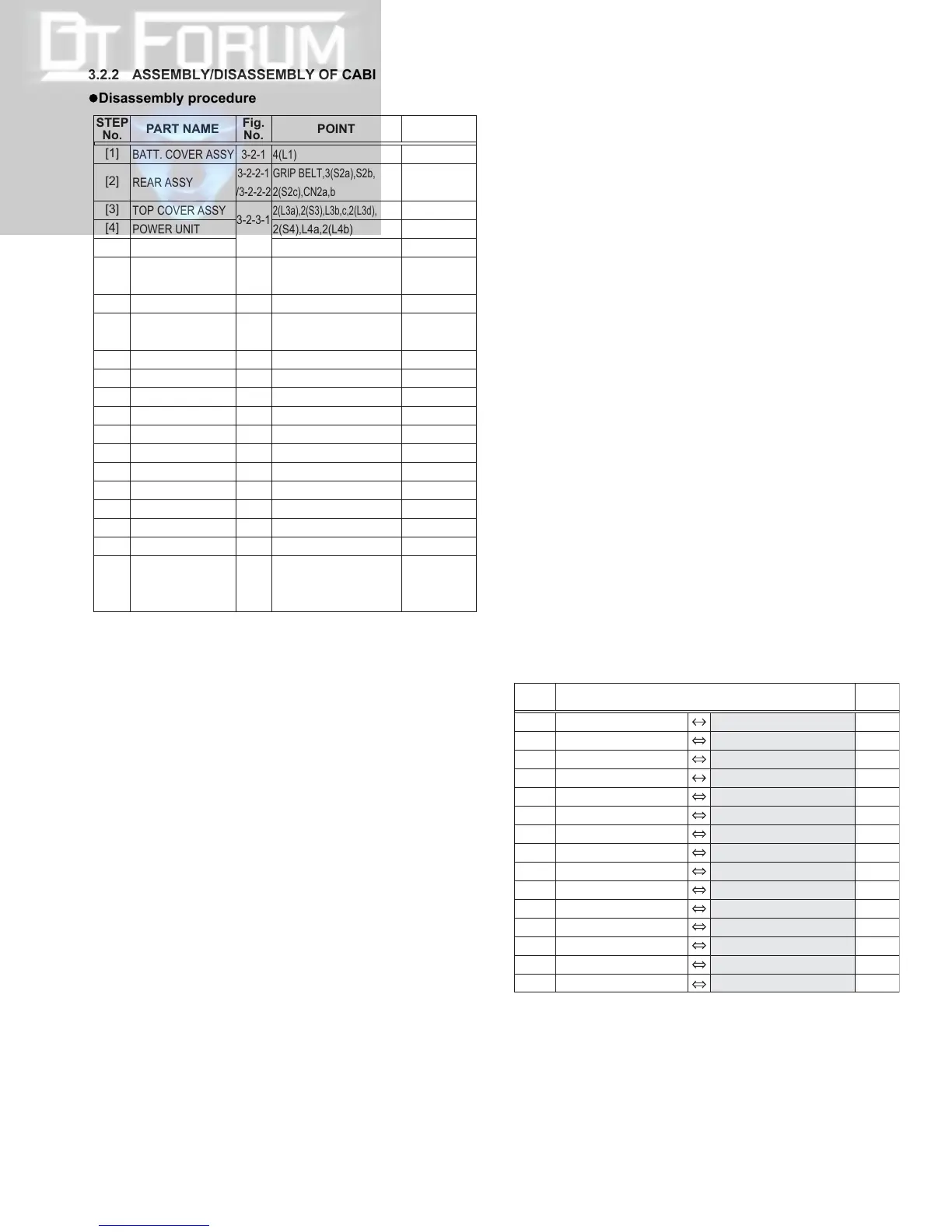
3.2.2 ASSEMBLY/DISASSEMBLY OF CABINET PARTS AND ELECTRICAL PARTS
zDisassembly procedure
NOTE2a:
Pull out the GRIP BELT from the HOOK first and leave it re-
leased.
NOTE2b:
When removing, press down the MONITOR ASSY first, and
then remove the 3 screws (1-3).
NOTE2c:
Refer to 3-2-2-1 DISASSEMBLY OF REAR ASSY for the
disassembly of the [2]REAR ASSY.
NOTE4:
When attaching, be careful with the wiring.
NOTE5:
When attaching, be careful with the wiring.
NOTE6:
When removing, remove the FRONT COVER ASSY and the
LOWER CASE ASSY together.
NOTE7:
When removing, remove the FRONT COVER ASSY and
the LOWER CASE ASSY together.
NOTE8:
When attaching, be careful with the wiring.
NOET9:
When attaching, avoid putting FPC (SENSOR) in between
by folding it toward the MAIN BOARD.
NOTE11:
Refer to 3.2.3 ASSEMBLY/DISASSEMBLY OF [11] OP
BLOCK ASSY for the disassembly of the [11] OP BLOCK
ASSY
NOTE14a:
When removing, peel off the FPC first to release it from the
ARM ASSY.
NOTE14b:
During the procedure, be careful in handling the parts.
NOTE17:
When attaching, tighten the screws in the reverse order of
removing the screws.
NOTE18a:
When attaching, fold and place the FPC inside the COVER
(SWING).
NOTE18b:
When attaching, avoid damaging the LED by firmly pressing
it into the COVER.
NOTE19a:
When removing, slide the MONITOR ASSY to the direction
of the arrow.
NOTE19b:
During the procedure, be careful in handling the PLATE
(GRIP BELT) as it becomes free.
NOTE20a:
When removing, remove the screws 47 and 48 first, and
then remove the screws 49 and 50 on the other side.
NOTE20b:
When attaching, first put the FPC through the hole and then
pull out the FPC.
NOTE21a:
Disassemble the MONITOR ASSY if necessary. During the
procedure, pay special attention not to damage or soil the
surface.
NOTE21b:
LCD SA consists of three parts (SHIELD (MONI), LCD
MODULE, and LCD CASE). During the procedure, pull out
the whole unit before disassembling.
zDestination of connectors
BATT. COVER ASSY
REAR ASSY
TOP COVER ASSY
POWER UNIT
SPEAKER
FRONT COVER ASSY
/LOWER CASE ASSY
MIC
BOTTOM CASE ASSY
/BTU BOARD ASSY
BTU BOARD ASSY
OP BLOCK ASSY
BOTTOM CASE
ARM ASSY
CASS COVER ASSY
ZOOM UNIT
MAIN BOARD ASSY
MECHANISM ASSY
REAR BOARD ASSY
COVER(SWING)
REAR SWING ASSY
MONITOR BOARD ASSY
STEP
No.
PART NAME
Fig.
No.
POINT NOTE
[1]
[2]
[3]
[4]
[5]
[6]
/[7]
[8]
[9]
/[10]
[10]
[11]
[12]
[13]
[14]
[15]
[16]
[17]
[18]
[19]
[20]
[21]
4(L1)
GRIP BELT,3(S2a),S2b,
2(S2c),CN2a,b
2(L3a),2(S3),L3b,c,2(L3d),CN3
2(S4),L4a,2(L4b)
L5
2(L6a),S6a,2(S6b),S7a,S7b
2(L6b),L6c,L7,CN7
2(S8),PLATE MIC
2(S9a),S9b,CN9
3(S10)
CN11a,2(S11),CN11b
S12
CN13,2(L13a),4(S13),L13b,c
4(S14),4(L14)
2(S15),2(L15)
CN16a,b,c,d,e,S16,L16a,b,c
4(S17),FRAME ASSY
2(S18),2(L18),CN18
3(S19)
2(S20a),2(S20b)
CN21,S21,L21a,2(L21b),
SHIELD(MONI),
LCD MODULE,LCD CASE
3-2-1
3-2-2-1
/3-2-2-2
3-2-3-1
/3-2-3-2
3-2-4-1
/3-2-4-2
3-2-4-3
3-2-5
3-2-6
3-2-7
3-2-8
3-2-9
3-2-10
3-2-11
3-2-12
3-2-13
3-2-14
3-2-15
3-2-16
3-2-17
-
NOTE2a,b,c
-
NOTE4
NOTE5
NOTE6,7
NOTE8
NOTE9
-
NOTE11
-
-
NOTE14a,b
-
-
NOTE17
NOTE18a,b
NOTE19a,b
NOTE20a,b
NOTE21a,b
CN2a SPEAKER - REAR CN404 2
CN2b REAR CN108 MAIN CN111 39
CN3 POWER UNIT - MAIN CN106 6
CN7 MIC - MAIN CN2601 4
CN9 BTU CN501 MAIN CN101 26
CN11a CCD CN5001 MAIN CN4201 20
CN11b OP BLOCK ASSY - MAIN CN4901 26
CN13 ZOOM UNIT - MAIN CN501 6
CN16a SENSOR - MAIN CN1604 16
CN16b
LOADING MOTOR/R.ENC
- MAIN CN1601 8
CN16c HEAD - MAIN CN3501 8
CN16d
DRUM MOTOR
- MAIN CN1602 11
CN16e CAPSTAN MOTOR - MAIN CN1603 18
CN18 MONITOR CN7702 REAR CN109 22
CN21 LCD MODULE - REAR CN7701 40
CN.
No.
PIN
No.
CONNECTOR

 Loading...