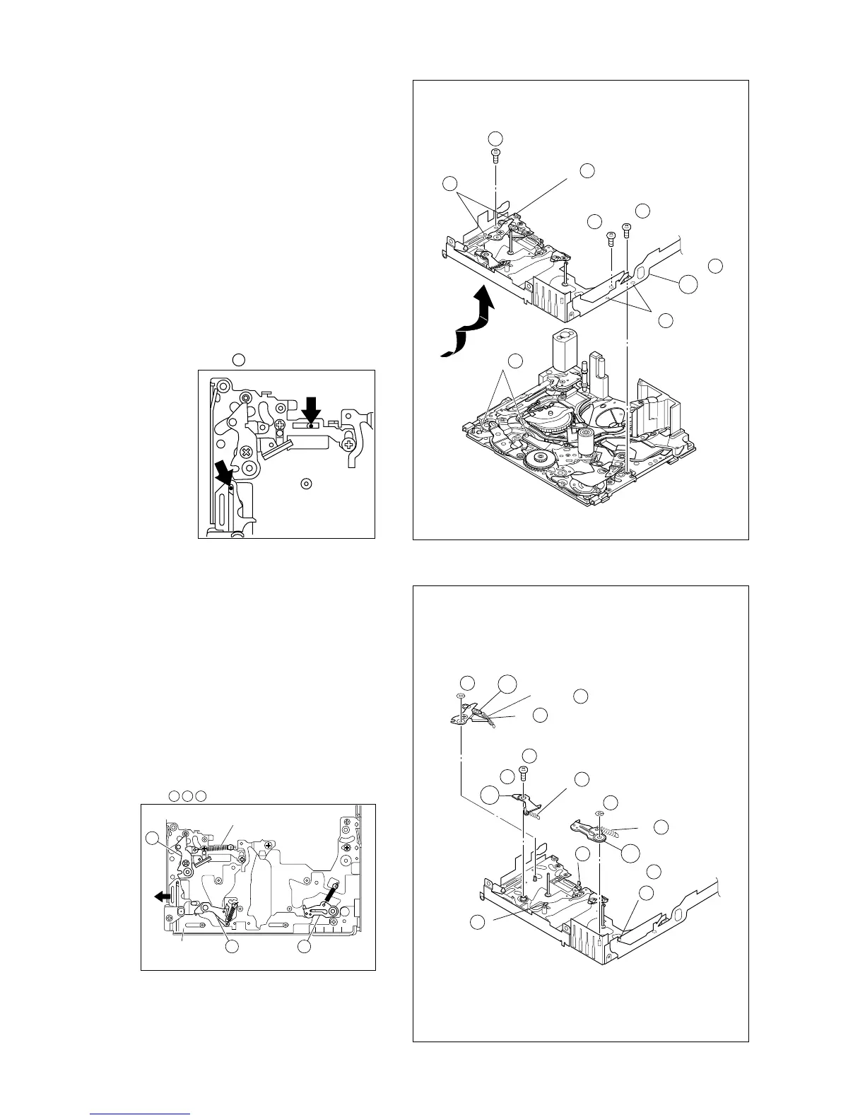
2-9
Fig. 2-4-7a
Fig. 2-4-7b
5.
!
SLIDE DECK ASSY
6.
@
PAD ARM ASSY
#
SUP BRAKE ASSY
$
TU BRAKE ASSY
11
(S b)
14
11
(S a)
12
11
(S a)
13
11
(L b)
11
(L a)
11
(L c)
11
NOTE a
11
NOTE b
11
(W )
12
(P )
12
12
(P )
14
(W )
14
(L )
13
(L )
12
(L )
14
14
(P )
13
13
(S )
13
15
NOTE
14
NOTE
12
NOTE
13
NOTE
11
b
NOTE
!
a:
Each of the parts on the SLIDE DECK ASSY can be re-
placed separately.
When detaching the assembly, if there is no need to replace
any of its parts, remove the SLIDE DECK ASSY as it is.
NOTE
!
b:
When mounting, pay attention to the positions of the
¤
SLIDE LEVER (2) studs and the
(
BRAKE CONTROL LE-
VER ASSY.
When mounting, position the CONTROL PLATE on the left
side.
Pay attention to the position of the SLIDE GUIDE PLATE
during mounting.
NOTE
12 13 14
12
13 14
SPRING
CONTROL
PLATE
NOTE
@
:
The spring may have already been disengaged when the
8
SLANT POLE ARM ASSY was removed.
NOTES
$
:
When mounting, pay attention to the correct positioning.
Mount the CONTROL PLATE by moving it fully toward the
left side.