3-2
1. Torque driver
Be sure to use to fastening the mechanism and exte-
rior parts because those parts must strictly be control-
led for tightening torque.
2. Bit
This bit is slightly longer than those set in conventional
torque drivers.
3. Tweezers
To be used for removing and installing parts and wires.
4. Chip IC replacement jig
To be used for adjustment of the camera system.
5. Jig connector cable
Connected to CN107 of the main board and used for
electrical adjustment, etc.
6. Extension connector
Connect this extension connector to the connector of
the jig connector cable for extending the cable con-
nector.
Note :
For supplying the power through the coupler by
removing the cover (for jig), use this
extension connector double for connecting the
jig connector cable.
7. Communication cable
Connect the Communication cable between the PC
cable and Jig connector cable when performing a PC
adjustment.
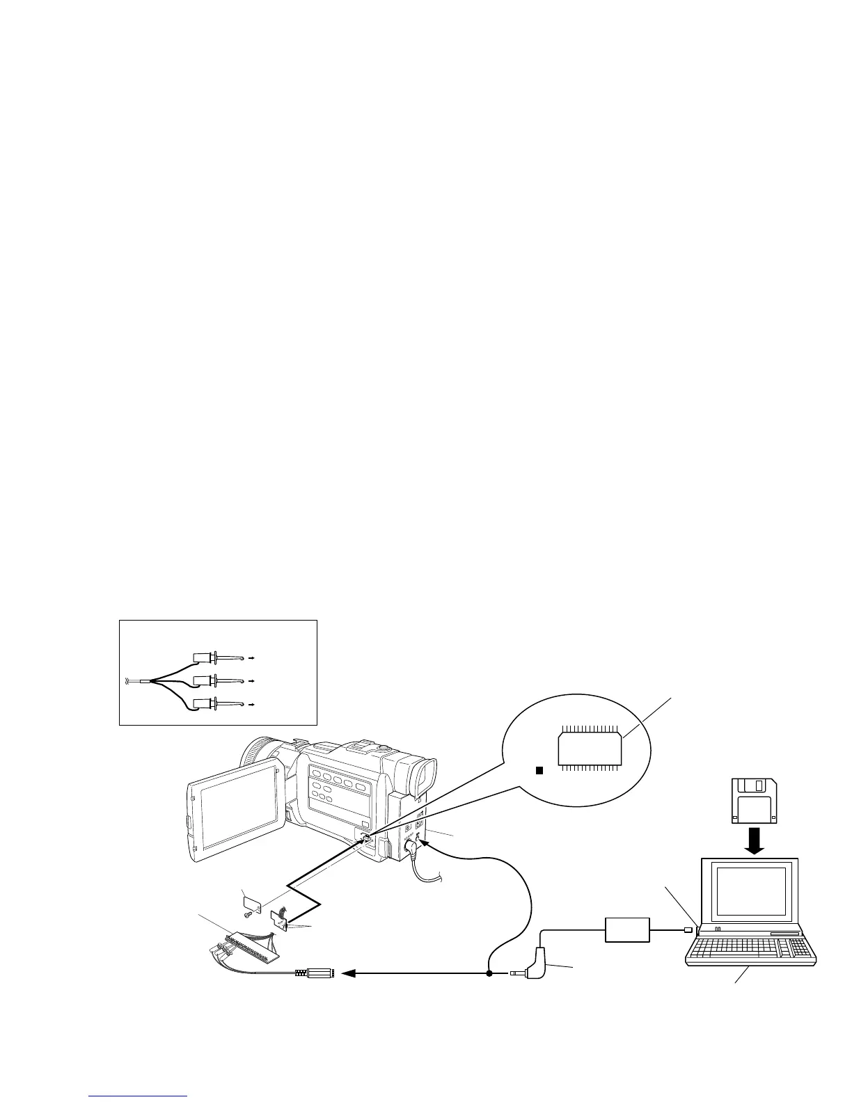
3.2 SETUP
1. Setup for electrical adjustment with personal computer
Fig. 3-2-1 Connection for Service support system
8. PC cable
To be used to connect the VideoMovie and a personal
computer with each other when a personal computer
is used for adjustment.
9. Alignment tape
To be used for check and adjustment of interchange-
ability of the mechanism.
10. Service support system
To be used for adjustment with a personal computer.
11. INF adjustment lens
To be used for adjustment of the camera system.
12. INF adjustment lens holder
To be used together with the camera stand for operat-
ing the VideoMovie in the stripped-down
condition such as the status without the exterior parts
or for using commodities that are not yet conformable
to the interchangeable ring.
13. Camera stand
To be used together with the INF adjustment lens
holder.
14. Light box assembly
To be used for adjustment of the camera system.
15. Gray scale chart (for Light box assembly)
To be used for adjustment of the camera system.
16. Color bar chart (for Light box assembly)
To be used for adjustment of the camera system.
EXTENSION CONNECTOR
Removing the cover (for jig),
use this extension connector double
for connecting the jig connector
cable.
NOTE:
COVER
(JIG)
JIG CONNECTOR CABLE
1
JACK BOX
MENU
30
TL2005
MONI CHG
16
15
1
Service Support
System software
RS232C
COM Port
PC CABLE
Personal Computer
CN107
(JIG CONN.)
RED
to 8 pin
( JLIP_RX )
WHITE
BLACK
to 9 pin
( JLIP_TX )
to 5 or 23 pin
( GND )
COMMUNICATION CABLE JIG CONNECTOR