3-3
3.3 MONITOR ADJUSTMENT
Notes :
Unless otherwise specified, all measurement points
and adjustment parts are located on MONITOR
board.
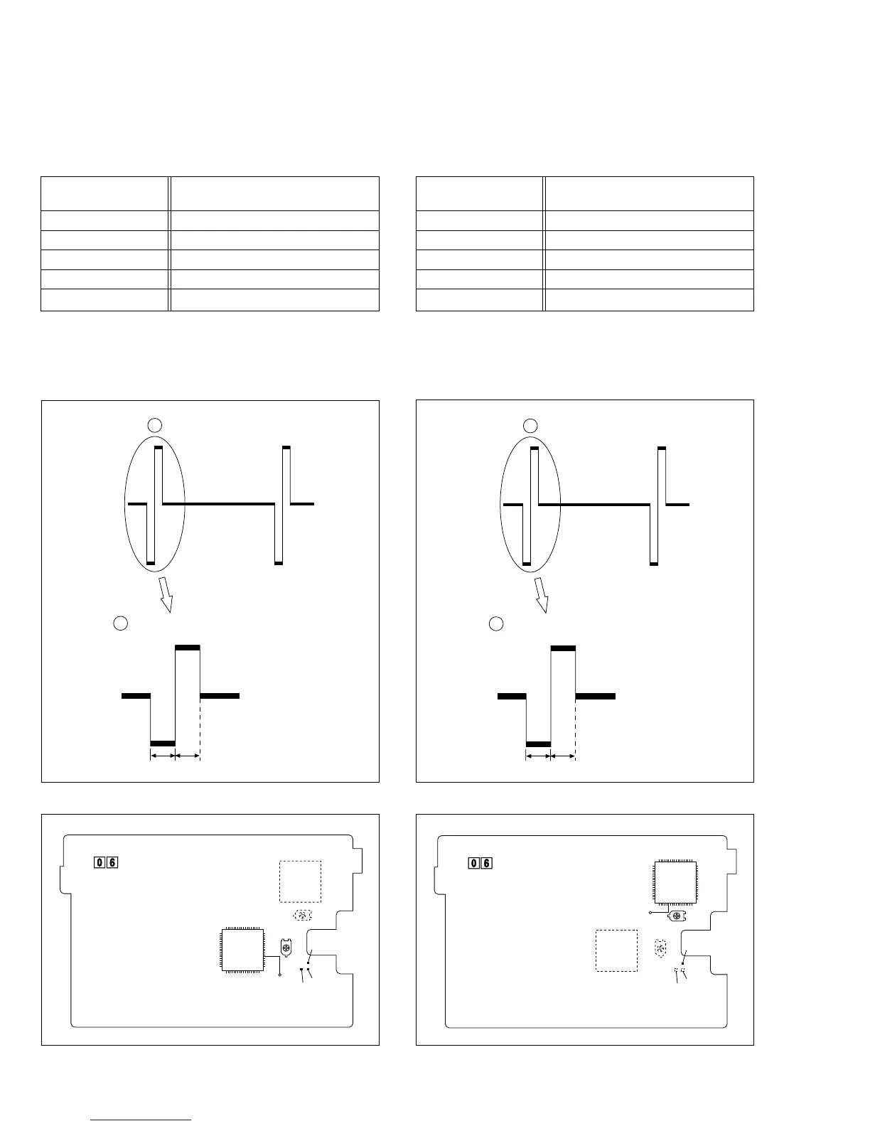
1) Observe waveform at pin 24 of the IC7301 or TP7301
(RPD).
2) For the wavefor shown in the waveform chart (Fig. 3-3-
1), equalize the width of A and B with each other by ad-
justing R7321.
3.3.1 PLL (MONI)
a
a
H. rate
< magnification>
A = B
AB
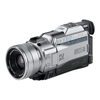
Fig. 3-4-1 PLL (VF)
a
H. rate
AB
< magnification>
A = B
a
Fig. 3-3-1 PLL (MONI)
Subject •Camera picture
•Gray scale
Mode •EE
Equipment •Oscilloscope
Measurement point •
IC7301 pin 24 (RPD) or TL7301 (RPD)
Adjustment part •R7321 (PLL MONI)
Specification
•A = B
3.4 ELECTRONIC VIEWFINDER (E.VF) ADJUSTMENT
Notes :
Unless otherwise specified, all measurement points
and adjustment parts are located on MONITOR
board.
1) Observe waveform at pin 24 of the IC7401 or TL7401
(RPD).
2) For the wavefor shown in the waveform chart (Fig. 3-4-
1), equalize the width of A and B with each other by ad-
justing R7421.
3.4.1 PLL (VF)
Subject •Camera picture
•Gray scale
Mode •EE
Equipment •Oscilloscope
Measurement point •
IC7401 pin 24 (RPD) or TL7401 (RPD)
Adjustment part •R7421 (PLL VF)
Specification
•A = B
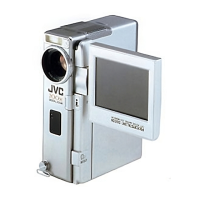
Fig. 3-3-2 MONITOR board (COMPONENT SIDE)
R7421
PLL(VF)
55
54 37
24
(PRD)
81
72
36
19
R7321
PLL(MONI)
TL7401(PRD)
TL7301
(PRD)
TL7302
IC7301
IC7401
MONITOR PWB
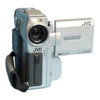
Fig. 3-4-2 MONITOR board (COMPONENT SIDE)
R7421
PLL(VF)
1
72 55
3619
18
54
37
R7321
PLL(MONI)
IC7301
IC7401
MONITOR PWB
24
(PRD)
TL7401(PRD)
TL7301
(PRD)
TL7302