2-9
Fig. M5
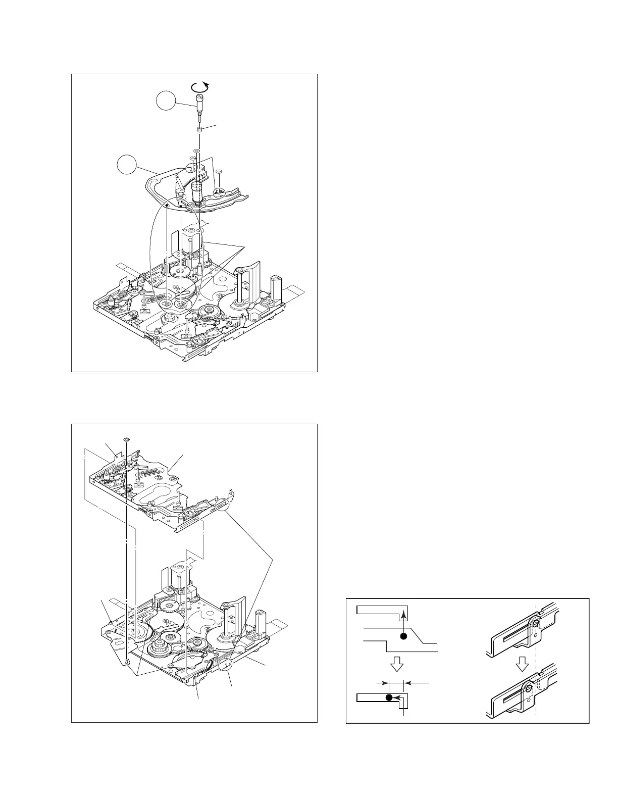
5. @ Guide roller (SUPPLY) assembly/ # Rail assembly
Note 7:
When removing the rail assembly, remove the guide roller
(SUPPLY) assembly beforehand.
Note 8:
Pay careful attention to the spring not to lose it.
Note 9:
Pay careful attention to the engagement of the rail assembly’s
arm ends because they easily come off the engagement.
Moreover, make sure that there is neither deformation nor
damage observed in them.
Note 25:
When removing the rail assembly, check to see if the collar is
securely set in the arm groove.
Fig. M6
6. B Slide deck assembly/ C Main deck assembly
Note 10:
When removing the slide deck assembly, pay heed to the three
components of the following because they are apt to come off
after the slide deck assembly is removed.
w
Tension lever assembly/ e Slide lever assembly
r
Brake control lever assembly
For reassembling those components, refer to Fig. M8 on page
2-10.
Note 24:
When reassembling the slide deck assembly to the main deck
assembly, combine them with each other by the side grooves
and then slide the slide deck assembly by 1 mm or so.
13
(W1)
(W1)
(W1)
(P3)
Note 8
Note 7
Note 9
Note 25
12
CMain deck
assembly
BSlide deck assembly
(L7)
(L8)
(L10)
(L9)
Note 24
Note 10
(W1)
 Loading...