5
4
3
2
1
A
BC
DE
F
G
2-27 2-28
C2404
CN27
IC2401
REG_3.2V
Q2401
C2402
C2403
R2402
R2401
R2403
PA_SIG
A_MUTE
GND
L2401
C2401
SPK-
SPK+
NJM2149V-X
DTC144EE
/6.3
#
/6.3
T
0.1
1.0
4.7
3.9k
10k
47µ
47
0 1
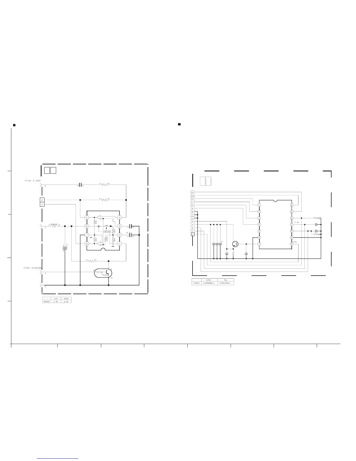
MAIN(SPEAKER)
MAIN(SPEAKER)
SCHEMATIC DIAGRAM
y40119001a_rev0.1
NOTE : The parts with marked() is not used.
NOTES : ٨For the destination of each signal and further line connections that are cut off from this diagram,
refer to "BOARD INTERCONNECTIONS".
٨When ordering parts, be sure to order according to the Part Number indicated in the Parts List.
C5307
C5302
C5301
IC5301
CN5301
Q5301
R5302
C53
0
R530
C530
R530
C5305C5306
/25
VO
#
H1
H2
V4
V3
V2
V1
GND
GND
GND
CCD_OUT
CCD_HV
SUB
CCD_LV
RG
QGF0523F1-14W
2SC3931/CD/-X
T
1.5
0.1
5.6k
2200p
1MW
0.1
27p
V4
V3
V2
NC
GND
V1
H2
H1
RG
SUB
NC
VDD
VL
0
2
CCD
y40120001a_rev0.1
CCD SCHEMATIC DIAGRAM
NOTES : 1. The parts with marked() is not used.
2. For CCD waveforms,please refer to page 2-43.
NOTES : ٨For the destination of each signal and further line connections that are cut off from this diagram,
refer to "BOARD INTERCONNECTIONS".
٨When ordering parts, be sure to order according to the Part Number indicated in the Parts List.
٨IC5301 is incorporated in the CCD base assembly.
When IC5301 needs replacement, replace the CCD base assembly in whole becaouse it cannot
be replaced alone.