(No.YD023)1-7
Fig.4-2f
4.3 Electrical adjustment [VHS SECTION]
Note:
The following adjustment procedures are not only neces-
sary after replacement of consumable mechanical parts
or board assemblies, but are also provided as references
to be referred to when servicing the electrical circuitry.
In case of trouble with the electrical circuitry, always be-
gin a service by identifying the defective points by using
the measuring instruments as described in the following
electrical adjustment procedures. After this, proceed to
the repair, replacement and/or adjustment. If the required
measuring instruments are not available in the field, do
not change the adjustment parts (variable resistor, etc.)
carelessly.
4.3.1 Servo circuit
4.3.1.1 Switching point
<UJ,UM Model>
(1) Play back the signal (A1) of the alignment tape (A2).
(2) Apply the external trigger signal to D.FF (E) to observe
the VIDEO OUT waveform and V.PB FM waveform at
the measuring points (D1) and (D2).
(3) Set the VCR to the manual tracking mode.
(4) Adjust tracking so that the V.PB FM waveform becomes
maximum.
(5) Set the VCR to the Auto adjust mode by transmitting the
code (F) from the Jig RCU. When the VCR enters the
stop mode, the adjustment is completed.
(6) If the VCR enters the eject mode, repeat steps (1) to (5)
again.
(7) Play back the alignment tape (A2) again, confirm that the
switching point is the specified value (G).
<UA Model>
(1) Play back the signal (A1) of the alignment tape (A3).
(2) Perform the above steps (2) to (6).
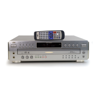
Fig.4-3a Switching point
4.3.1.2 Slow tracking preset
(1) Record the signal (A2) in the mode (B1), and play back the
recorded signal.
(2) Set the VCR to the manual tracking mode.
(3) Set the VCR to the FWD slow (+1/6x) mode.
(4) Transmit the code (F) from the Jig RCU to adjust so that the
noise bar becomes the specified value (G) on the TV mon-
itor in the slow mode.
(5) Set the VCR to the Stop mode.
(6) Confirm that the noise bar is (G) on the TV monitor in the
slow mode.
<UA Model>
(1) Record the signal (A3) in the mode (B2), and play back
the recorded signal.
(2) Repeat steps (2) to (6) .
Note:
• For FWD slow (+1/6x) playback, transmit the code "43-08"
from the Jig RCU to enter the slow playback mode, and
transmit the code “43-D0” for REV slow (+1/6x) mode.
4.3.2 Syscon circuit [UA, UM MODELS]
Notes:
• When perform this adjustment, remove the Mechanism
assembly.
4.3.2.1 Timer clock
(1) Connect the frequency counter to the measuring point (D1).
(2) Connect the short wire between the short point (D2) and
Vcc (5V).
(3) Short the leads of capacitor (D3) once in order to reset
the microprocessor of the Syscon.
(4) Disconnect the short wire between the short point (D2)
and Vcc then connect it again.
(5) Adjust the Adjustment part (F) so that the output frequency
becomes the specified value (G).
Signal (A1)
(A2)
(A3)
• Stairstep signal
• Alignment tape(EP,stairstep,NTSC) [MHP-L]
• Alignment tape(LP,stairstep,PAL) [MHPE-L]
Mode (B) • PB
Equipment (C) • Oscilloscope
Measuring point (D) • VIDEO OUT terminal (75 ohm terminated)
• TP106 (PB. FM)
External trigger (E) • TP111 (D.FF)
Adjustment part (F) • Jig RCU: Code “43-5A”
Specified value (G) • 6.5 ± 0.5H
Adjustment tool (H) • Jig RCU [PTU94023B]
Alignment tape
[SP, stairstep]
played with the
SP head
Alignment tape
[EP(LP), stairstep]
played with the
EP(LP) head
Drum side Control head position Capstan side
X-value adjustment point
Maximum
Waveform output
Signal (A1)
(A2)
(A3)
• Ext. input
• Color (colour) bar signal [NTSC]
• Color (colour) bar signal [PAL-N]
(UA Model)
Mode (Notes)
(B1) • SP/EP
(B2) UA Model
• SP/LP
Measuring point (D) • TV-Monitor
Adjustment part (F) • Jig RCU: Code “43-71”or “43-72”
Specified value (G) • Minimum noise
Adjustment tool (H) • Jig RCU [PTU94023B]
Signal (A1) • No signal
Mode (B) • EE
Equipment (C) • Frequency counter
Measuring point (D1)
(D2)
(D3)
• IC3001 pin 44
• IC3001 pin 103
• C3054 + and -
Adjustment part (F) • C3025 (TIMER CLOCK)
Specified value (G) • 1024.008 ± 0.001 Hz
(976.5549 ± 0.0010 usec)
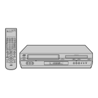
V.sync
Trigger point
Switching point
V. rate
 Loading...