1-8 (No.MA429<Rev.002>)
SECTION 3
DISASSEMBLY
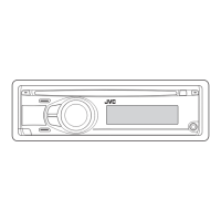
3.1 Main body (Used figure are KD-A305)
3.1.1 Removing the Bottom chassis (See Fig.1, 2)
(1) Remove the two screws A and one screw B attaching the
Heat sink. (See Fig.1)
(2) Remove the two screws C, two screws D and one screw E
attaching the Bottom chassis and then slide to backward
the Bottom chassis. (Se Fig.2)
Fig.1
Fig.2
3.1.2 Removing the Front chassis (See Fig.3)
(1) Disengage four hooks a engaged both side of the Front
chassis.
Fig.3
3.1.3 Removing the Main board (See Fig.4, 5)
(1) Remove the two screws F and one screw G attaching the
side plate. (See Fig.4)
(2) Remove the three screws H attaching the Main board. (See
Fig.5)
(3) Disconnect the connector CN501
of the main board from
CD mechanism. (See Fig.5)
Fig.4
Fig.5
AA B
CCDD
E
hook a
FFG
H
CN501
H