EasyManua.ls Logo

JVC KD-G120R

JVC KD-G120R
63 pages
To Next Page IconTo Next Page
Loading...
SERVICE MANUAL
COPYRIGHT © 2005 Victor Company of Japan, Limited
No.MA233
2005/12
CD RECEIVER
MA233200512
KD-G120,KD-G120R,KD-G123,
KD-G124,KD-G125,KD-G126,
KD-G161,KD-G162
Lead free solder used in the board (material : Sn-Ag-Cu, melting point : 219 Centigrade)
TABLE OF CONTENTS
1 PRECAUTIONS . . . . . . . . . . . . . . . . . . . . . . . . . . . . . . . . . . . . . . . . . . . . . . . . . . . . . . . . . . . . . . . . . . . . . . . 1-6
2 SPECIFIC SERVICE INSTRUCTIONS . . . . . . . . . . . . . . . . . . . . . . . . . . . . . . . . . . . . . . . . . . . . . . . . . . . . . . 1-9
3 DISASSEMBLY . . . . . . . . . . . . . . . . . . . . . . . . . . . . . . . . . . . . . . . . . . . . . . . . . . . . . . . . . . . . . . . . . . . . . . 1-10
4 ADJUSTMENT . . . . . . . . . . . . . . . . . . . . . . . . . . . . . . . . . . . . . . . . . . . . . . . . . . . . . . . . . . . . . . . . . . . . . . . 1-13
5 TROUBLESHOOTING . . . . . . . . . . . . . . . . . . . . . . . . . . . . . . . . . . . . . . . . . . . . . . . . . . . . . . . . . . . . . . . . . 1-14
Area suffix
J ------------- Northern America
KD-G120,KD-G120R
Area suffix
E ------------- Southern Europe
EX ------------ Northern Europe
EY ------------- Eastern Europe
EU ------------------------- Turkey
KD-G161,KD-G162
Area suffix
UI ---------------------------- India
KD-G123,KG-G124
Area suffix
UT ------------------------- Taiwan
UH ---------------------- Thailand
UN --------------------- Indonesia
U -------------------- Other Areas
KD-G125,KD-G126
KD-G125
KD-G126
KD-G120RKD-G120
KD-G123 KD-G124
KD-G125 KD-G126
KD-G161 KD-G162
KD-G162
KD-G161
w
w
w
.
x
i
a
o
y
u
1
6
3
.
c
o
m
Q
Q
3
7
6
3
1
5
1
5
0
9
9
2
8
9
4
2
9
8
T
E
L
1
3
9
4
2
2
9
6
5
1
3
9
9
2
8
9
4
2
9
8
0
5
1
5
1
3
6
7
3
Q
Q
TEL 13942296513 QQ 376315150 892498299
http://www.xiaoyu163.com

Other manuals for JVC KD-G120R

Question and Answer IconNeed help?

Do you have a question about the JVC KD-G120R and is the answer not in the manual?

JVC KD-G120R Specifications

General IconGeneral
BrandJVC
ModelKD-G120R
CategoryCar Receiver
LanguageEnglish

Summary

Service Manual Title and Model Information

CD Receiver Model Identification

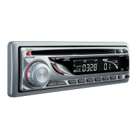
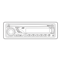
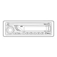
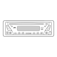
Lists specific JVC CD Receiver models covered in the manual.

Product Specifications

Audio Amplifier and Tuner Specifications

Details power output, impedance, frequency response, sensitivity, and selectivity.

CD Player and General Specifications

Covers CD player performance, power requirements, dimensions, and operating conditions.

Safety and Precautions

General Safety Warnings

Warns about chassis burrs, laser beam exposure, and static electricity hazards.

Handling the Optical Pickup Unit

Provides guidelines for handling the sensitive laser pickup and preventing ESD damage.

Laser Product Safety Compliance

Details Class 1 Laser Product warnings and safety switch requirements.

Service and Disassembly Procedures

Specific Service Instructions

Refers to external manuals for CD mechanism service procedures.

Unit Disassembly Guide

Step-by-step instructions for dismantling the main body, covers, and chassis.

Component Removal Procedures

Guides on removing side panels, main boards, rear brackets, and CD mechanisms.

Switch Board Removal

Instructions for detaching the switch board from the front panel.

Adjustment and Troubleshooting

Adjustment Method and Setup

Lists required instruments and measurement conditions for unit adjustment.

Troubleshooting: KD-G120 Series

Diagnostic flowcharts for common issues in the KD-G120 model range.

Troubleshooting: KD-G161 G162 Series

Diagnostic flowcharts for troubleshooting the KD-G161 and KD-G162 models.

Laser Pickup Maintenance

Covers cleaning, life expectancy, and replacement procedures for the laser pickup assembly.

Wiring Diagrams

16-Pin Cord Diagram: KD-G120 KD-G120 R

Pinout and function details for the 16-pin connector on specific models.

16-Pin Cord Diagram: KD-G123-KD-G126

Pinout and function details for the 16-pin connector on KD-G123 to KD-G126 models.

16-Pin Cord Diagram: KD-G161 KD-G162

Pinout and function details for the 16-pin connector on KD-G161 and KD-G162 models.

Schematic Diagrams

Block Diagrams: KD-G120 Series

High-level system overview showing major functional blocks and connections.

Standard Schematics: KD-G120 Series

Detailed circuit diagrams for tuner, MICOM, power amp, and CD sections.

Block Diagrams: KD-G161 KD-G162 Series

System block diagram illustrating the architecture of KD-G161/G162 models.

Standard Schematics: KD-G161 KD-G162 Series

Detailed circuit diagrams for main board and CD servo control sections.

Printed Circuit Board Layouts

Visual layouts of components on the main and switch printed circuit boards.

Parts List

Exploded View of General Assembly

Illustrates the product's physical assembly with numbered parts for identification.

Electrical Parts List: Main Board (KD-G120 Series)

Comprehensive listing of electronic components for the main board.

Switch Board Parts List

Lists components for the switch board, including LEDs, diodes, and resistors.

Packing and Accessories List

Details included manuals, accessories, and packing materials for product shipment.

Related product manuals